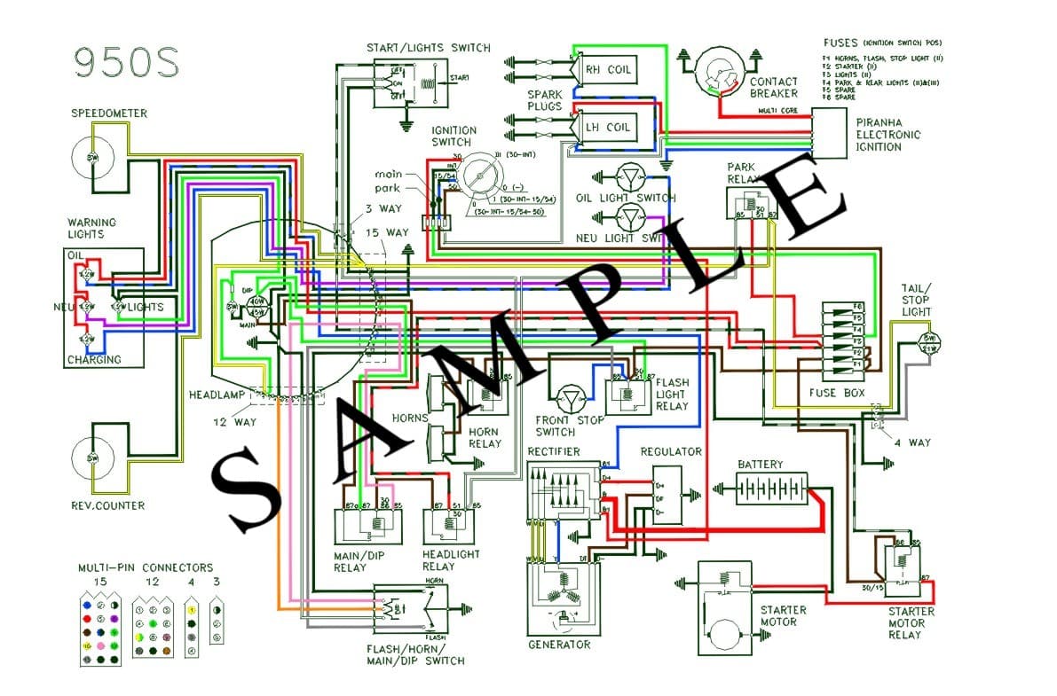
There is a relay already for the flash headlight circuit, on the LH switch the grey wire goes to earth when it is pressed, this is connected to terminal 85 and activates the relay which connects the fuse F1 (this is fed from 15/54 terminal on the ignition switch) via relay terminal 30/51) to the headlamp dip beam (green wire from relay terminal 87). As the relay activation current is very low only a small current passes through the LH switch.
The horn is very similar, but might not have a relay, yet. You can add a similar switching relay into the circuit. Pressing the horn button earths the black wire in the LH switch, which needs to connect to terminal 85 on the new relay. Terminal 30/51needs a live feed connect this to the fuse F1 (this is fed from 15/54 terminal on the ignition switch) or from the flash light relay terminal 30/51. Finally connect the brown wire from the horn(s) to terminal 87 of the horn relay and the black wire from the horn(s) to earth.
The lights are more complicated, I have connected the light switch to two separate switching relays, as for the horn and flash, one for the headlamp and clocks and the other to the parking light and tail light. The second relay is probably unnecessary as there is not a lot of current drawn by the park and tail lights.
Starting with the park lights relay the activating earth to terminal 85 comes from the LH switch yellow wire, terminal 30/51 is the main power from fuse F4 (this is fed from INT terminal on the ignition switch) and terminal 87 is connected to the yellow wires to the rear light and pin 10 in the 15 way connector in the headlamp shell. This will connect it to the parking light but not the LH switch yellow wire, as noted above.
The headlight relay again is a standard switching relay, the feed to terminal 85 comes from the green wire in the LH switch, 30/51 is the main power via black/red wire from fuse F3, (this is fed from 15/54 terminal on the ignition switch) and terminal 87 is connected to the green wire to pin 9 in the 15 way connector in the headlamp shell and also to pin 10 in the 15 way connector to connect to the clocks illumination lights and the dash light, but not to the park light.
Finally main beam relay again is a standard switching relay, the feed to terminal 85 comes from the brown wire in the LH switch, 30/51 is again the main power via black/red wire from fuse F3, (this is fed from 15/54 terminal on the ignition switch) and terminal 87 is connected to the brown wire to pin 6 in the 12 way connector in the headlamp shell.
Easy so far! I have not added the last relay as I no longer have a standard light switch, I have separate light switch (original kill switch on the RH switch) and a dip/main switch (original indicator switch on the LH switch) The output from the headlamp relay terminal 87, feeds to a changeover relay terminal 30/86. The switch connects terminal 85 to earth thus activating the coil in the relay and switching the main load between two outputs terminal 87 (dip - green wire) and terminal 87a (main beam - brown wire). There are therefor no large amperages on the contacts in the handlebar switches.
The other difference on my bike is that I have left all of the yellow wires in the headlamp connected to the park light relay, it was easier to wire that way and as I never intend on leaving the bike with the parking light on, but it passes an MOT, it is not a problem to leave the clock and dash lights connected this way.
I told you it was simple! I can send you a sketch if it would help.
This is my set up
Best wishes Chris