# V50 Electrical P10 Red Wire and Future Proofing.
**URL:** https://forum.motoguzziclub.co.uk/t/v50-electrical-p10-red-wire-and-future-proofing/24746
**Category:** Small Block V Twins (not new V7s)
**Created:** [23 September 2026 15:55 UTC](https://forum.motoguzziclub.co.uk/t/v50-electrical-p10-red-wire-and-future-proofing/24746 "2026-09-23T15:55:47Z")
**Posts on this page:** 7
**Page:** 1
### Author:  [@FletchG](https://forum.motoguzziclub.co.uk/u/FletchG)
#### Post date: [23 September 2026 15:55 UTC](https://forum.motoguzziclub.co.uk/t/v50-electrical-p10-red-wire-and-future-proofing/24746/1 "2026-09-23T15:55:47Z")
I’ve just finished a total rebuild, however on 3rd ride out I lost all electrical power. Connecting the fuse board direct to the battery, effectively bypassing the ignition switch restored power (Garage playing later and not sure if this would be good for the alternator with the engine running).
I suspected the Pin 10 corrosion/burn out issue.. but what had happened is that there is a break in the red wire somewhere at or just below the ignition switch. My inclination is to either solder a new 2.5mmsq wire to the ignition switch terminal, or if this looks good, crimp a new wire on just below is and run this to the battery side of P10, with a good waterproof connector; I’d appreciate any thoughts or experience on this.
---
### Author:  [@DaiG](https://forum.motoguzziclub.co.uk/u/DaiG)
#### Post date: [23 September 2026 17:35 UTC](https://forum.motoguzziclub.co.uk/t/v50-electrical-p10-red-wire-and-future-proofing/24746/2 "2026-09-23T17:35:18Z")
It’s feasible, but you might also want to consider trying the following. Solder a new wire onto the end of the old one and pull it through the wiring harness, then cut off the old wire and terminate the new one as needed. A lot neater.
---
### Author:  [@FletchG](https://forum.motoguzziclub.co.uk/u/FletchG)
#### Post date: [23 September 2026 18:02 UTC](https://forum.motoguzziclub.co.uk/t/v50-electrical-p10-red-wire-and-future-proofing/24746/3 "2026-09-23T18:02:11Z")
Now that is a good idea, thanks Dai!! and I’ll definitely give that a go. Cheers Gareth
---
### Author:  [@FletchG](https://forum.motoguzziclub.co.uk/u/FletchG)
#### Post date: [15 October 2026 14:29 UTC](https://forum.motoguzziclub.co.uk/t/v50-electrical-p10-red-wire-and-future-proofing/24746/4 "2026-10-15T14:29:05Z")
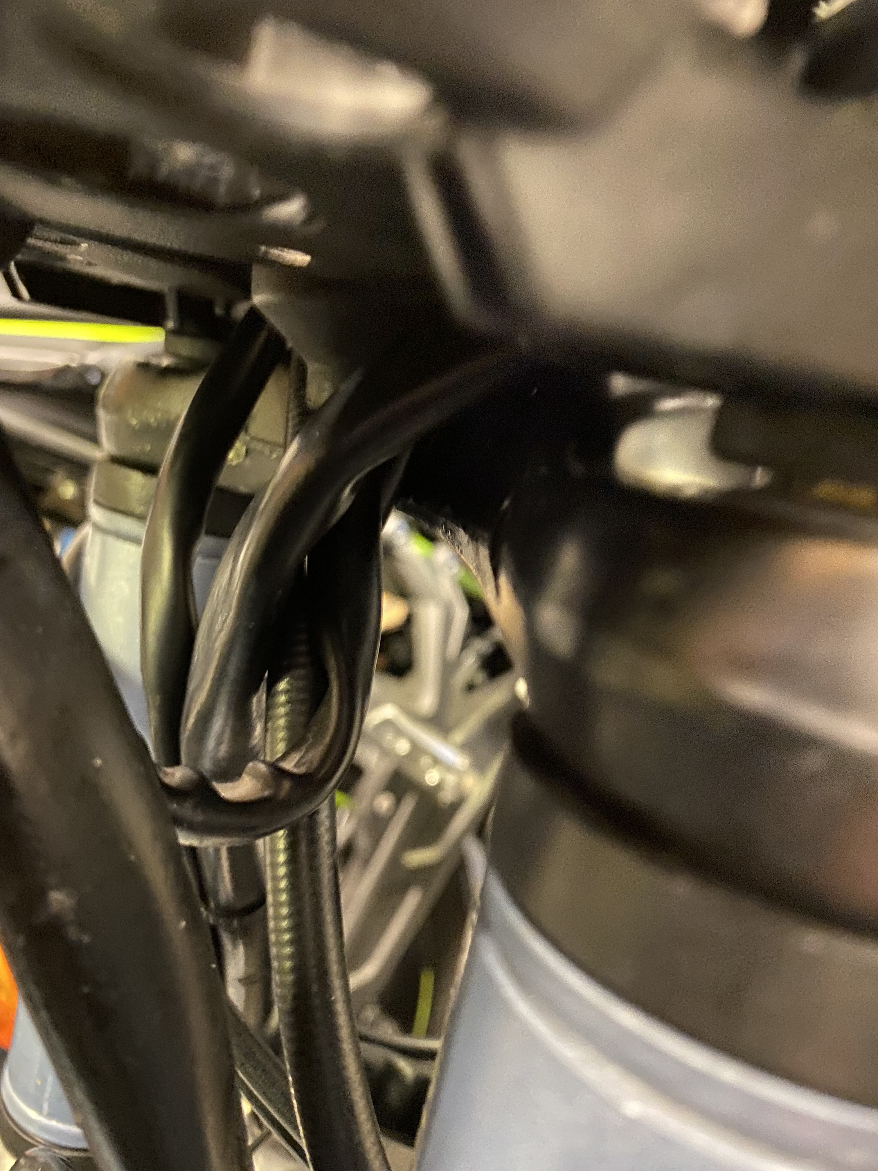
Quick update; not red wire at all, rather operator error on reassembly.
The return (brown) wire from the ignition switch had become detached from the rear of the ignition switch… same result. Now as to why it became detached, my best judgement is that, on reassembly, I did not pass the cable bundle from the left handlebar switch through the ignition switch loop, result, said ignition switch ‘loop’ was pushed against the clutch cable behind the clocks and had been progressively worked loose.
---
### Author:  [@FletchG](https://forum.motoguzziclub.co.uk/u/FletchG)
#### Post date: [15 October 2026 14:32 UTC](https://forum.motoguzziclub.co.uk/t/v50-electrical-p10-red-wire-and-future-proofing/24746/5 "2026-10-15T14:32:20Z")
---
### Author:  [@DaiG](https://forum.motoguzziclub.co.uk/u/DaiG)
#### Post date: [16 October 2026 09:01 UTC](https://forum.motoguzziclub.co.uk/t/v50-electrical-p10-red-wire-and-future-proofing/24746/6 "2026-10-16T09:01:46Z")
Yah well. BTDT too. The spade terminal switches seem to be particularly prone to leaving home.
---
### Author:  [@FletchG](https://forum.motoguzziclub.co.uk/u/FletchG)
#### Post date: [16 October 2026 09:29 UTC](https://forum.motoguzziclub.co.uk/t/v50-electrical-p10-red-wire-and-future-proofing/24746/7 "2026-10-16T09:29:24Z")
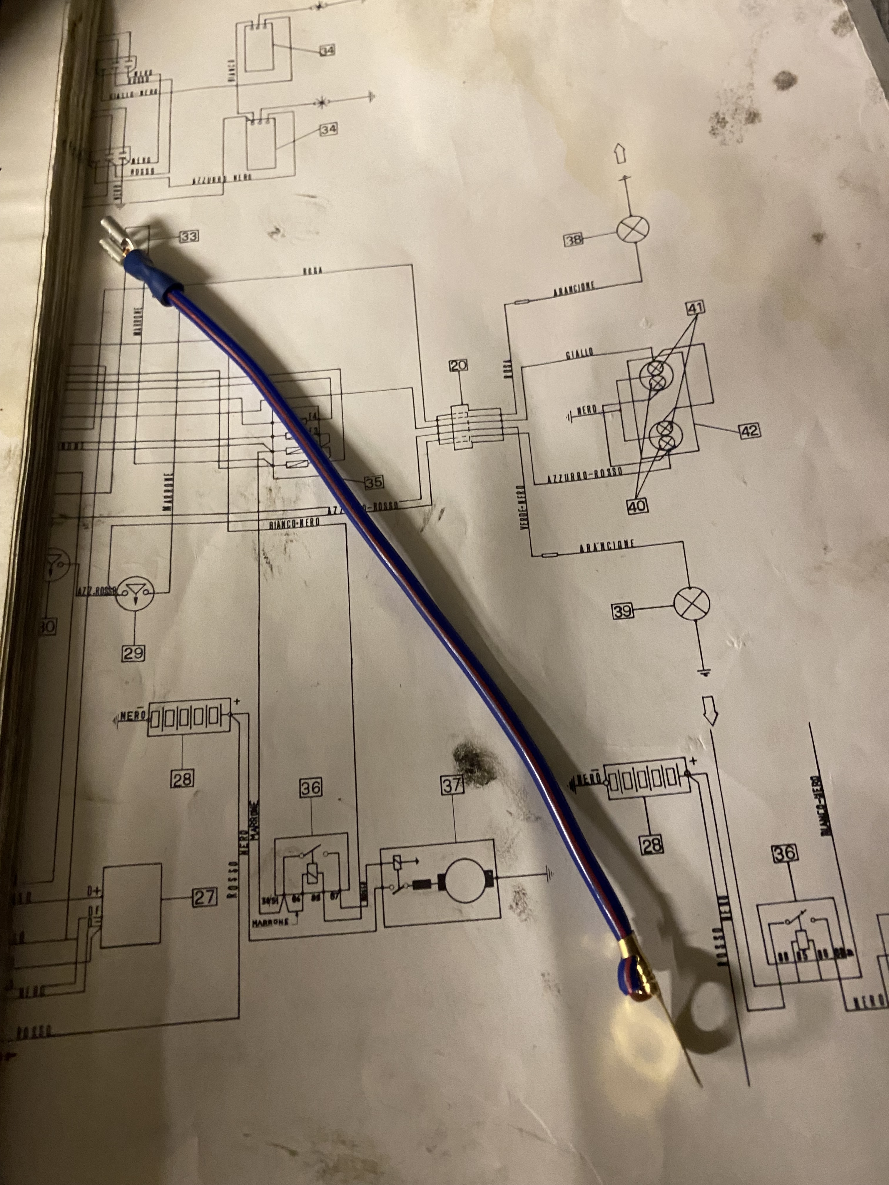
Hey ho… anyway, given this and still the potential for Red Wire failure, I have added the following component to the tool kit… connects battery +ve directly to fuse board feed side… effectively hot wiring the bike.
In fact with a fuse added and maybe a bit longer, it could also address the ‘click no start’ known issue? Great fun resolving the inaccurate wiring diagram too, see my other current post.