V50II not charging: the brushes and rotor have been replaced but I need to check the output but have a huge blind spot when it comes to electrical stuff - do I test across each of the 3 yellow wires and earth?
Cheers
Hi.
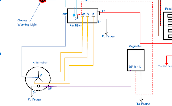
I presume that you have three yellow wires, one per phase.
You should be able to connect a volt meter on an AC range. Try between each yellow wire in turn. If you number the wires 1,2 & 3 you will test 1-2 2-3 1-3. Im not exactly sure of the value but it will be higher than 15V. All readings should be similar. Increasing revs should increase the voltage.
In fact I’ve just thought that you may only have two wires. If that’s the case just measure across these.
Let us know your findings.
Cheers
Phil
I bet your diode board is at fault, easy to repair for somebody with knowledge, all I can say… But follow the path from the manual, this at least will give you some confidence what is what. Priceless when on the road!
Hi Phil. I tested between the 3 yellow wires last night and got 0V, which made me wonder whether I was doing it correctly.
I’m going to try again in daylight today as it was getting a bit murky when I did it….
Mmmm.
Continuity test next to check winding resistance. Again go between each winding. Should be just a few ohms each.
Err, I assumed that you have it disconnected from the regulator whilst testing.
Ah, no. And there’s a demonstration of my ignorance when it comes to electrics! I’ll try again…… and test for continuity
The advice from Dave Richardson in Guzziology
The stator requires a little residual magnetism in order to work. If never magnetized, or if left unused for long periods, the rotor can require a brief connection with a twelve-volt power source. Simply flash two battery leads to the two slip rings.
Ah ha, the diagram is great.
Unplug the yellow wires from the rectifier pack and then you can do the resistance check.
The alternator needs field current from the regulator to generate ouput. So DF needs to be connected when testing for voltage.
1 Like
I disconnected the plug onto the 3 yellows and got 0V but continuity seems ok across all 3 at 0.1 ohms….
Ok . Seems low. Ill check mine at lunch time.
Need to check if the field windings are being powered from the regulator.
What voltage have you got between DF and ground.
I would also disconnect DF and check resistance from DF on the alternator and ground. This should be a few homes.
I’ve just looked at ours. It’s only single phase without a field coil so a lot different to yours.
The coil measures 0.3ohm and 45Vac when reved a little.
So I have about an ohm from DF to ground and 3V per phase across the yellows.
With the ignition on and DF connected what DC voltage between DF and ground?
Without enough voltage here there isn’t enough magnetism to generate AC voltage at the yellow wires.
You can check voltage at each yellow to the blue centre with the engine running. The higher the revs the higher the voltage.
Hi Phil, apologies for the delay - work and other stuff got in the way……… so, DF to Earth with ignition on (but engine not running) is about 1V so I guess not enough…… something needs to be replaced I suspect?
Not sure what you mean by the ‘blue centre’ though
There are a couple of good guides to testing the charging system.
Bosch chargingsystem fault finder
Charging around the circuit
Thanks Don. I have that printed out, but being a complete dimwit when it comes to electrics, I don’t know how to test the system. It’s a never-ending source of stress but no matter how much I look at these things, it may as well be written in ancient Sanskrit!!!
And for some reason ive not seen your replies, sorry.
Yes that’s not enough.
The field voltage comes from the regulator. It varies the voltage to regulate the output of the alternator.
Have a look at the voltages going into the regulator.
Also the blue wire i referred to is the MP connection on the diode pack.
Until you have sufficient field voltage the output will ne too low.
Where are you in the world? We’re in Manchester but Jane’s family are around Colwyn Bay so we go often.