I have removed the stator coil so I can get to the nuts on the inside to release the brushes holder (see other thread) and will replace it with a new coil that I bought many years ago thinking that was the charging problem, which I have now discovered is the rotor! I should have read Guzziology first!
Anyway as to my question, the three wires from the coil are soldered to a three spade connector on the alternator casing which are marked U, V and W. Is there any order that these must be fitted as there is no difference between the three wires coming from the coil.
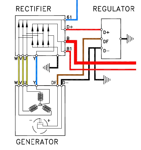
The three yellow wires go to the rectifier where they all eventually connect to terminal B and so to the battery, and to B1 and off to the ignition switch, also all connect to terminal 61 and from there to the charging light. So is there any order or can they connect to the output three gang connector?
As Mike_H says. Each yellow wire is connected to a single phase that produces an AC waveform. The rectifier doesn’t care in what order it receives the AC waveform; it just converts it to DC and passes the DC pulse on to the regulator to be smoothed out. Don’t forget to reconnect the centre-tap wire (blue). It’s not a disaster if you do but you’ll find yourself about twenty watts down on maximum output.
After testing the Ohms I had my V50 rotor windings re-done for voltage reasons. I would think that if you followed the diagram as they are in a straight line it would not matter if they were crossed over. (An ohm (symbol: Ω) is the standard unit of electrical resistance. It shows how much a material or device slows down the flow of electric current. One ohm of resistance means that a voltage of one volt makes a current of one amp flow).
Chris forgive me if Im teaching my Grandma to suck eggs but make sure terminal 61 is connected to the lamp as this energies the rotor. If you use an Led, one must use a 68 ohm resistor in parallel.