Can anyone advise please what the correct order is for the wiring on the Breva 750 starter relay connector?
In trying to carry out the starter relay mod to cure sluggish starting, I somehow mixed up two wires when re-inserting the blade connectors into the plug.
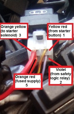
They are wire 3 that feeds the solenoid and wire 5 that provides power to the relay.
I am not sure if their position in the photo is right or are they upside down?
Thought I’d also be clever and replace the standard wire 3 with a much thicker one (the red one in the picture) to carry current to the solenoid. However, all I seem to have done is make a cock-up of the whole thing.
As the wire colours are virtually indistinguishable when plugged into the relay on the bike, I made a sketch of their positions within the connector before pulling out the spades, using the clip hoop as a reference point. But after some problems with the starting, I reverted back to what I thought was the original set-up. However, my drawing didn’t tally with the position of the other two wires which I had not removed! I think I made the sketch from the front of the plug after taking it off, but had obviously re-fitted the wires from the back.
Bizarrely though, the engine starts with the wires in either position, but one of them must be using the relay the wrong way around.
So can anyone confirm what the correct wiring is on that starter relay plug please?
I’ve gone though the wiring diagram methodically to see how the other relays are wired, but with typical Italian flair they don’t match up exactly to the diagram!
The other lesson here of course is if it ain’t broke don’t fix it! All along, the sluggish starting has been down to both batteries I use for the Breva being duff. A small lithium ion battery I tried as a last resort turned the engine over faster than I have ever heard it!
I also think I will change that chunky wire back to the original, tiny as it is, as I believe that modern wiring carries a far greater load than older stuff (which that red wire is).
Cheers
Mark
I’m not that familiar with the newer bikes, but this is an image I saved some time ago regarding the relay upgrade if that helps. Are the relay terminals numbered to match those in the picture?
Looking at Don’s diagram 5 is to the starter solenoid and not 3. If the plug is rotated 180 degs the starter wire (earth) and the supply wire would be swapped and the starter would not work.
In the extract of the wiring diagram below component 36 is the starter relay, there is no garuantee that the colours are correct as I do not have the original factory wiring diagram to hand, this one is drawn by Carl Allison and sometimes the colous get changed in the translation from Italian.
Terminal 1 (yellow/red wire) is feed to the actuating coil in the relay
Terminal 2 (purple wire) is from the adjacent safety logic relay (whatever that is) and that is the earth to the actuating coil in the relay.
Terminal 3 (red/yellow wire) is the feed to the starter solenoid, activated by the relay
Terminal 5 (orange/red wire) is the feed from the battery via the ignition switch and fuse box
If you turned it around by 180 degs you woul swap terminals 1 & 5 and 2 & 3 (from your numbering) and it would not work as terminal 2 is an earth and terminal 3 is the supply to the starter. You may fry the wires though!
Where did you find the terminal numbers? Are they on the relay?
Thanks guys.
I got all the numbers from the handbook wiring diagram, with number 36 being the starter relay. However, those numbers do not appear on the relay itself, nor on the plastic plug connectors.
When I compared the sequence of the wiring on the plugs of all the other relays on the bike to see if I could work which way around they should be, two of them are in a different order, and some of the colours don’t match either. This is presumably why Guzzi fit plug connectors which can only go in one way - until some twit takes the spades out to modify it!
So all I need is the sequence of wiring into the white plastic plug that goes into that relay number 36, based on looking at the relay in the same position as the picture with the clip at the top. I know that 1 and 2 are OK on the right as I never touched them, so it’s only whether 3 should be next to the yellow and red wire as it is in the picture, or next to the violet wire.
Mine is an 06 model Breva, but I’m not aware of any changes to wiring for later models.
Cheers.
If 1 and 2 are as they should be then 3 and 5 can be either way around. 1 and 2 power up the coil in the relay that makes an electromagnetic fiels that opperates the switch inside the relay that sends power to the starter solenoid. The relay is joining wires 3 and 5 when the starter button is pressed. I would think they can be either way round.
The idea of the relay wiring upgrade is to provide a good strong power feed to the relay terminal that is used to supply the solenoid. This should be direct from the battery (via a fuse). In normal Guzzi wiring, this feed goes via the ignition switch and through at least two block connectors. Over time these all get a bit corroded and build up resistance causing voltage drop and the all too familair click, no crank.
I am assuming the two power feeds into the relay are the red/yellow wires. One feeding the starter button and the other to the solenoid.
If you put the new live feed onto the wrong red/yellow terminal, then the starter will operate with the ignition off.
If you get the correct one, it won’t.
I started that upgrade but found the original power supply wire had an alarm wire spliced into it. The upgrade I tried was with a separate relay to provide the 12v power to the starter relay. I was able to use the alarmed wire into that relay instead. However, I took it off after only getting a clunk when pressing the starter button, thinking I’d cocked up the wiring and not realising it was actually the battery that was duff. I will see how the starter works with a new AGM battery, but it turned over much quicker with the lithium one I tried after reverting to the standard relay set-up.
Using a relay to power a relay that operates a Solenoid (another type of relay) is a bit overkill.
The general way to improve reliability of the starter circuit is to run a direct feed from the battery to the relay on the secondary side so it gives max voltage to the solenoid.
You can leave the alarm fed from the old red/yellow wire.
Terminal 1 (red/yellow) is power feed from the starter button to activate the relay, only live with the ignition on.
Terminal 2 (purple wire) is an earth, so when the starter button is pressed the relay is opperated and a connection is made between terminals 3 and 5 unlike the earlier models the earth is not at the handle bar starter button, the power comes from the starter button and it is earthed through terminal 2 and through the “B safety logic relay” which I assume is either the side stand or neutral switch. Earlier Guzis had a live feed to the relay and the starter button earthed it to make the relay work.
Terminal 3 (red/yellow) is the feed to the starter solenoid
Terminal 5 (red/orange wire) is the feed from the battery, via the fuse box and the ignition switch
There is no live feed to that relay that is not via the ignition switch. Terminals 3 and 5 are open normally but connected together when the starter button is pressed and the relay activated, so I see no reason why the wires to terminals 3 and 5 cannot be swapped. Mark if you are worried about this I would wait for someone with the same model to post a picture of this relay for you. The heavy wire you have connected to terminal 3 is not required as there is no large current between the relay and the starter solenoid. What Don describes about the supply going through loads of connectors that can get oxydised is absolutly true and it would appear from the wiring diagram that this is still the case with your model.
The idea of the starter relay wiring upgrade is to provide a strong power supply to feed the solenoid. This needs to be direct from the battery (through an in line fuse). It is not standard, but it is a huge improvement to the reliability of the starter circuit as the solenoid gets the full battery power, not a weakened one that has been through the ignition switch and a couple of block connectors that all cost precious volts.
…but if the wiring and connections are maintained there is no need to run this mod wire straight from the battery. I agree the fewer the connections the better the supply is, but on my bike the mod wire to the starter relay is from the fuse box via the ignition switch and not direct from the battery (with an in line fuse) so as when I turn my bike off, I like it to be off. Then of course there is my Stelvio, and I havent started playing around with that…yet!
I have done the modification to my Spada as that was click no starty when I bought it 30 odd years ago. The Cali wiring is still standard at present and generally works OK, but it will get changed if it starts messing me about.
All sorted!
I checked the connectors when the tank was off and they are fine. I am now back to all the original wiring on the relay, and satisfied the wires are in the correct place.
After fitting a new battery I also checked the voltage at the relay input. It was less than a quarter of a volt drop from the battery, which sounds pretty good to me bearing in mind it goes up to the ignition, all the way back again and through the fuse before getting to the relay. It now fires up almost instantly on the button.
Thanks for your input, much appreciated.

