Can anyone out there help me with the wiring of the rear brake light switch on the Cardellino 73. The wiring diagram shows one terminal of the switch goes to earth (that is the easy bit!). there are then two black wired shown going to the second terminal. One goes to the rear light itself (again, easy to understand). the second black wire id shown coming from the generator. My bike only has the red (rosso) and green (verde) wires coming from the generator. My question is where does the black (nero) wire originate from?

As far as I can tell it is also an earth, I think it goes to the generator casing. The yellow (giallio) wire is the +ve feed and the switch earths the black wire completing the circuit.
Wire number 3 in the menu to the right “cavo nero del volano all’interruttore d’arresto” Google translate gives me “black flywheel cable to the stop switch” and the line below “guaina in vipla di copertura di n. 3 cavi” translates as “vipla sheath covering n. 3 cables” Which I suspect means that it is a black earth wire from the stop switch to the generator and it is in a sleeve with two other cables, according to Wikapedia vipla means polyvinyl chloride in Italian!
Have fun ![]()
Thanks Chris. If wire 3 is is going to earth by implication wire 11 is also going to earth as they are both in the same terminal on the brake light switch. Then all the switch is doing is activating a second earth, ie wire 10. Using your logic, wire 3 is redundant, is it not? To add to the mystery there is a sentence in the electrical section of the workshop manual that says. “If the engine stops when the rear brake is operated the result we be a burned out stop lamp. It is therefore necessary to replace it.” Does that help in a further diagnosis? I am not sure how one is supposed to stop the engine as it has no kill switch (either shown in the electrical schematic or, physically on the bike). The warning of the blown bulb suggests that if the engine is stopped with the brake light operating the bulb will receive an uncontrolled high voltage and blow the bulb. your further thoughts would be appreciated. Cheers Phil
I know this doesnt help much but I cant see wire 3 being connected to anywhere will help as the rear light needs a live feed to make it work. I assume the rear twin filament bulb works the same as the headlight bulb with its metal case earthed and two 6 volt lives needed to operate each filament. It does occur to me that the diagram may have errors (I have come across this before in a Ducati one) so does the brake switch have its original wiring still attached if so is it the same as the diagram?
You’ve just got to love old Italian elictrikery ![]()
CHRIS P
The feed is wire 9, the brake switch earths the light so turns it on.
http://www.thisoldtractor.com/guzzi007/pdfs/1958_Cardellino.pdf
English version
CHRIS P
Phil your logic is sound. So wire 3 must have another function, but I am not at all sure of what that is? I see that the numberplate illumination is shown in the rear light on the diagram Chris P has linked, this must mean that there is power there even when the brakes are not applied. I don’t see enough wires for that though, unless the action of the brake switch adds extra power to the rear light via wire 3. We need an expert!
Thanks Chris and Chris!
Just to clear up one thing. The rear light unit has two festoon bulbs in it. One is the rear light and it also acts as the number plate illumination. It uses the yellow, powered feed wire and is earthed to the chassis. this is powered when the light switch is operated. All simple stuff and easy to understand. The plot thickens, as if the yellow wire is only powered when the lights are “0n” then the brake light will only work when the lights are on, which obviously is not correct. the brake bulb needs a separate power feed and an earth. In that case wires 3, and therefore 11, must be powered all the time the engine is running. I am now thinking that the power must come from the ignition coil and not the lighting coil. does this explain why there is the warning, if the spark is “killed” and the brake light activated it will blow the bulb? The logic makes sense to me and the wiring diagram makes sense. I just need to find the evidence of wire 3 under the flywheel. Does this all make sense to you two??? Cheers Phil
My wife grew up in ZA and it all makes sense to her! Joking aside it makes sense to me too but I would wait for a second opinion!
http://www.guzziriders.org/cardellino-coil-testing_topic10192.html
The answer from GeorgeS may shed some light on the subject
CHRIS P
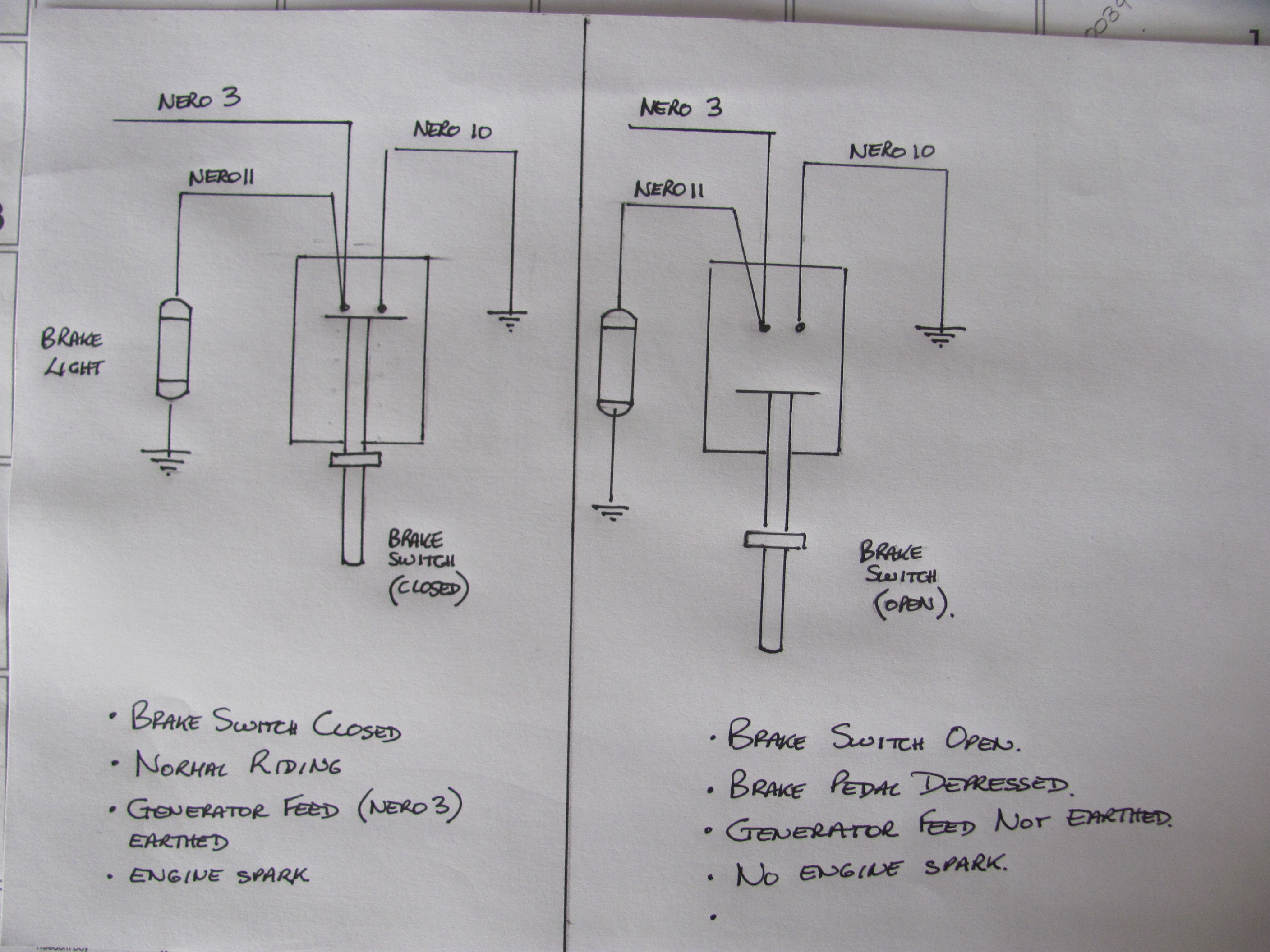
Thanks again to both of you. Having read the text on the link it makes sense. I was told that the in the early sixties it became law that all motorised vehicles had to have a brake light. this was made retrospective so many machines had to be retrofitted with brake lights and the method described was used by Moto Guzzi. I actually bought a new old stock updated rear light unit that contains the two bulbs which I assume was sold as part of the update kit along wit the brake switch. The switch actually bolts to the aluminium front section of the chain guard which looks like the real afterthought that it was! I have attached a schematic of the circuitry as per the original but with the brake switch shown in both its normal and operating positions. I assume that in the normal position the generator earth runs from wire 3 to wire 10 and the resistance create by the bulb in wire 11 is such that the bulb does not light up. (the electrical flow will take the path of least resistance). Once the brake pedal is operated the only way to earth is now via the brake light bulb which will now light up as the electrical flow has to pass through it. If this is the case (which it must be) then I assume that the spark will either be weakened or even stop. (There must be some Italian logic here in that when braking you will not require engine power!). Again, if this is the case then maybe this is the way to stop the motor ie press the brake pedal on tick over and the spark weakens and hence the motor will stop. The warning in the manual is still a little confusing. Maybe what it is actually saying is that if the brake light bulb has failed and the brake pedal is depressed than the motor will stop. This will be a fact. WOW all this for what should be a simple motorcycle!!!
Cheers Phil
I’m glad you have found the solution, strange though it may be!
Bloody hell only Moto Guzzi could come up with such a strange set up, but glad you sorted it
CHRIS P
I am afraid the saga continues. I have at least sorted out the handlebar light switch and have been able to get all functions to work. I started with a light switch that was totally disconnected and although the wiring diagram was available it did not indicate which wire went to which one of the seven terminals in the switch. with the switch being smaller than a matchbox it is not easy getting seven wires in and connected and this certainly adds to the frustration! However, an old auto electrician did offer some valuable advice. I did not know it but the terminal numbers cast into the bakelite are an old Bosch standard. 30 is battery, 58 is taillight, 57 is park light (front city light on the Cardellino), 56 is headlight power supply and 54 is horn. Useful info for anyone dealing with classic European bike rebuilds. Referring to the schematic above I can now put power to the green and red wires from the generator and all functions work. (all except the brake light!) However when connected to the generator only the horn, front city light and rear light work. (Handlebar switch in position !). When turned to position 2 the headlight and rear light do not function. The generator has two coils, one for HT ignition (this is working 100%) and one for lighting. Does the lighting coil have two windings, one for powering the city light and rear light (8 Watts in total) and the other for powering the headlight and rear light (28 Watts)? If that is the case I think one set of windings has failed. How do I check this? The rear brake light circuit is still a mystery. Where is it getting its power from? Could it be from a second winding on the ignition coil? I see no evidence of a third, black wire coming from either coil. How does the brake light operate when the switch shorts the power feed to earth under normal conditions and removes the earth when the pedal is operated? How can something so basic be so complicated???
Any answers would be gratefully received.
Many thanks
Phil
No idea myself, but there has ben an extensive conversation in the Google Guzzi singles group over the last few days about Cardellino electrics. It might help (unless you are already part of that conversation)
I do have an old hi / lo dip switch etc from that era I bought on eBay, not sure if it is going to be suitable for any of my projects if any use to you? I’ll try and find it and add a picture.
https://groups.google.com/forum/?nomobile=true#!topic/guzzi-singles/rOeDan5mIpQ
Thanks Don, I was not part of that discussion but it is all very familiar. The original question is basically the same as mine. it is a pity there is no definitive answer! I am battling to find a way to post an answer on the Google site, but I’ll sort that out today. You would think a 6 volt motorcycle with just a headlight, rear light, brake light and horn would be easy. Are you based near Northampton? I ask as my son took delivery of a Norge yesterday and he is in Northampton. Cheers Phil
Hi Phil,
With regard to your brake light conundrum; if I were you, I would abandon the original Moto Guzzi set-up and wire it in a way that will mean that you don’t stop the engine when applying the brake. This could have tragic consequences. Having a totally original bike is all well and good if you want to win prizes but personally I would opt for safety over originality every time. I would take a positive feed from the swich in the headlight rather than from the coil.
When I bought my Airone it didn’t have a rear light, but instead of fitting a correct rear light I bought one for a later bike. I want the car behind me to know when I am slowing down.
Hi Phil
I am a member of the group and get emails with each posting in the group. It gets a pain at times when a hot topic comes up, but they are easily deleted. To reply to a comment, I just reply to the email. It seems to work.
I am just up the road from Northampton in Market Harborough.
This is the dip / horn switch I have. Not sure if it is suitable?

Dip switch by Don West, on Flickr
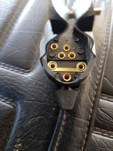
Dip switch by Don West, on Flickr
Thanks again Don. I got onto the site and posted a very long reply and question mail. your switch looks a bit different although it has the seven terminals so I guess it does the same functions. I think Mark has made an application to join the club and will probably attend the Northampton meetings once Boris lets you out to play again. Cheers Phil
The saga continues! No one has been able to come up with a definitive solution to my problem. (well it is not only me, but a number of others appear to have the same issue!). I did try using the power from the ignition coil. I tested if it would drive the brake light and it did, but of course when connected via the normally closed brake light switch I lost spark, so that idea was scrapped. I am now going to isolate the ignition coil, ie mount it on insulating washers and ensure it is not earthed via the fixing screws. I will then earth the coil via the brake switch. Now, when connected to the brake switch it will be earthed whilst the switch is closed and when the brake pedal is operated it will remain earthed but via the brake light bulb. I expect the spark will weaken but hopefully not enough to stop the motor. I’ll report back on the results tomorrow. Cheers Phil