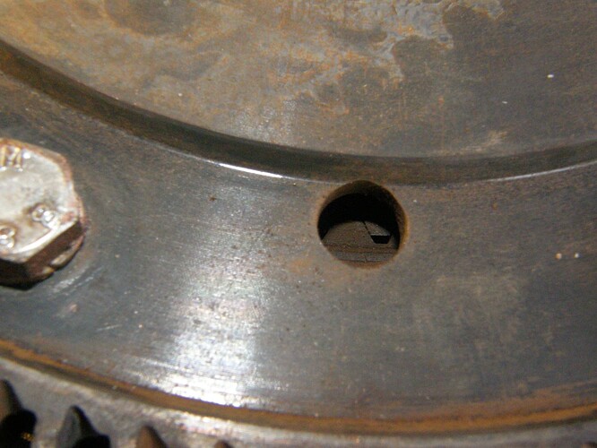
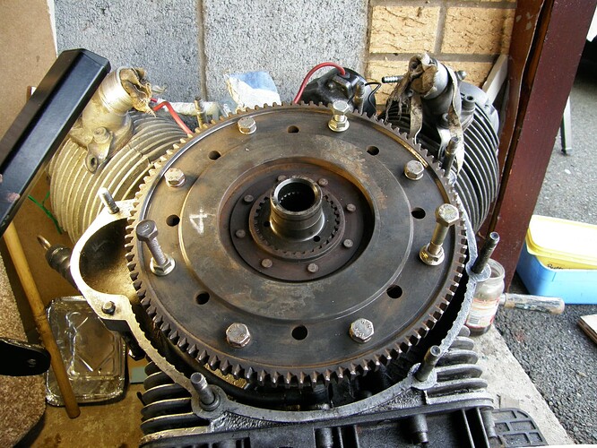
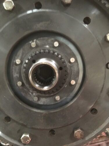
Can someone please tell me which mark(s) should be visible through the bellhousing aperture with either the left or right hand cylinder at TDC on the firing stroke?
Stupidly I’ve lost my painted reference marks on the flywheel and need to position it correctly before completing seal and clutch replacement. There are no visible factory references on the rear of the crankshaft or face of the flywheel.
Cheers,
Godfrey.
Im a bit limited for time spare so going to lift the r/h/s rocker to find the firing stroke and pop the box back on to see if I can get the ‘D’ visible in the timing aperture as I think this is probably the quickest and easiest solution to my stupidity of losing my paint mark on cleaning up the parts.
Think I’m right in the D mark on the flywheel circumference being for the right and S for the left cylinder?
Si. S=Sinistra/Left (think, Sinister, maybe?), D=Destra/Right
2 Likes
Watch out, marks are set quarter of a turn apart when you look at the flywheel. Undo LHS spark plug, set TDC ignition there. Unsure which TDC you’ve got, ignition or other one? Take a look at the pickup, it will be aligned, or nearly aligned there. Now, as you got it right, the flywheel will screw to the crankshaft this way:
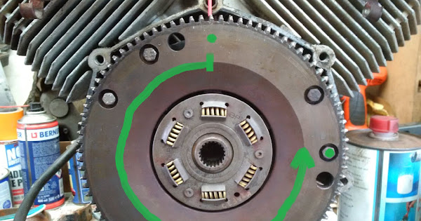
So: as the engine cranks counterclockwise, one set of stamps “looks out” through inspection window to the right, the other one, as green line shows, is delayed 270 degrees and is on the very top. No magic, once you learn it, you won’t forget. Enjoy!
2 Likes
Thanks for replies.
Got it on the firing stroke for the right cylinder and the ‘D’ aligned between the the two gearbox mounting studs and all good. 6 bolts so 6X60 degrees = 360 so must be right as 60 degrees out would be way out.
Checked valve clearances on both sides while at it.
Now just got to source some metric fine threaded rod to fit into the crank and draw up the pressure plate and compress the new springs.
Going to have to figure out how to ensure springs stay in alignment as i tighten it up as have crabbed the frame. Engine out would’ve been easier for this.
I have read the 6 bolts that attach the assembly to the crank are hi tensile steel as you don’t want them shearing when you dump the clutch. I reused the old ones when I rebuilt mine, with a spot of loctite for good measure.
1 Like
Yes Don. Matt black gives the clue. I also reused them with the correct torque + locktite too.
I wouldn’t have removed the flywheel but for wanting to renew all the seals and other clutch and input splined hub within the bell housing.
Now got to source a longer threaded rod and nuts to suit the thread in the crank end to compress the springs.
Incidentally the new clutch springs are an 1/8th longer than the ones that were there. Hopefully the clutch lever won’t be too much harder on the wrists.
As I’ve crabbed the frame the engine is lying as it would be in use. Any clues on how to ensure the springs stay in their slots? I’m thinking superglue 
When reassembling, bolt the inner plate to the crank with the 6 High tensile bolts, assemble the plates centrally using the gearbox spline to centre them. Not sure how you are going to hold the springs in place?
I used 3 long bolts and nuts to compress the springs, keep a very close eye on the outer splines as they drop into notches by looking through the small holes. I nudged them round as I compressed the springs very slowly. Don’t forget to put the centre piece back in.
Could you assemble the clutch, flywheel etc flat on the bench, then bolt the whole assembly to the crank?
You couldn’t reassemble the unit in one as the aperture within the first spring holding plate is too small to access the 6 high tensile bolts securing the flywheel to the crankshaft.Processing: 15829872-3CEA-4F14-9E8B-8448AC91EB0E.jpeg…
Processing: D8EB37AE-5993-45CF-8349-8904F11B4551.jpeg…
Processing: 085BFF09-5E01-44C5-BBA0-3F1E767F50D8.jpeg…
Gearbox is now back on with all necessary seals/clutch components replaced.
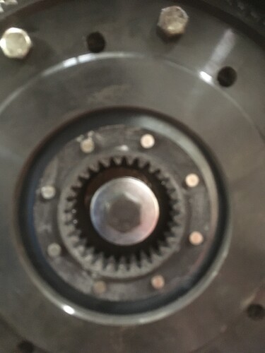
The central bolt into the crankshaft worked a treat as did a little superglue to temporarily hold the springs in place while it was being assembled.
Pictures to show, although our internet is pathetic and downloads a joke.
I thought it wise to check to see that the clutch disengaged the drive before all the rest of the assembly, and………………the bloody cable snapped🙄
So ordered 2 of them as I’m bound to need a spare as the replacements look a little lightweight compared to the rusty and frayed original in my spares box.
1 Like
Our internet takes a few minutes to download a single picture🙄
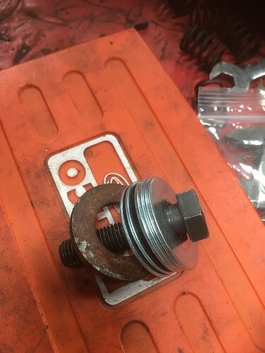
The M12 bolt has a particularly fine pitch that none of our local ironmongery stores had but a local bike shop recommended a try at tractor parts department which had the one needed.
Using the central bolt made it easy to apply just enough pressure to be able to evenly move the friction plates about.
The washers and length of thread on the bolt allowed enough compression so there was room to get the two clutch and one intermediate plate within the flywheel.
One of my manuals recommended a very light coat of graphite grease on the internal teeth of the flywheel. The only tube I could find was for a grease gun and priced at £37
I instead used a high temp resistant spray of molybdenum that dried within 10 minutes at a slightly cheaper rate of £15. Hopefully that’ll help run in the new components.
Two or more pictures at once seems to overload it.
Out of interest I first tried to use the old and worn gearbox input shaft for centralising the clutch components but couldn’t get it to engage in even the first clutch friction plate. No wonder the clutch was unable to disengage.
1 Like

