Hi all - I could do with a little help and advice, please.
I have a 1980 Le Mans 2, and I’ve got some (hopefully simple to fix) electrical gremlins.
It started with the indicator idiot lights failing, on both sides. The indicators themselves were working, but the display lights didn’t flash. I pulled the spade connectors off the dashboard to see if reseating them would solve the problem.
Unfortunately, it’s made things worse: I now have no idiot lights - the neutral, charging and oil lights no longer work. After some digging around, I was thinking of applying Stabilant 22 to the spade connectors - is this a good plan? Or is there something I’m missing with the connectors?
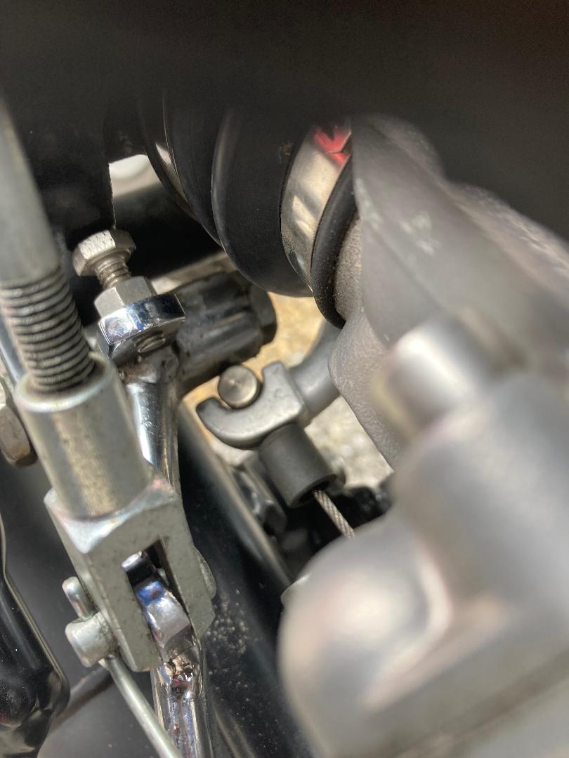
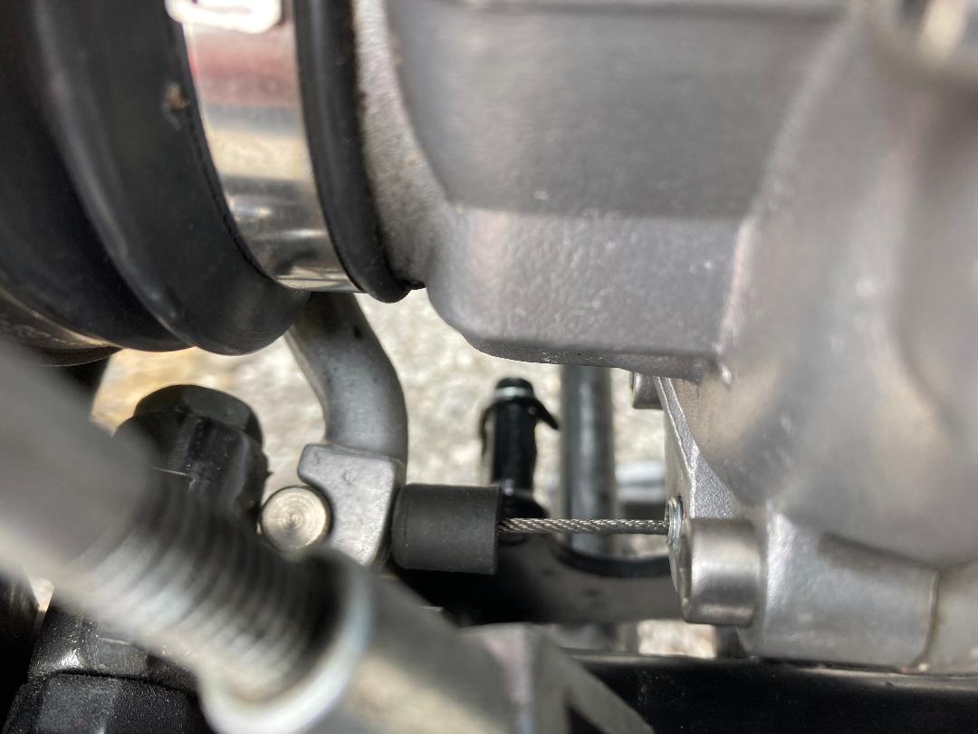
I also have an issue with the clutch, in that the bike creeps slightly when it’s in gear and the clutch pulled lever in. I’ve tried adjusting the clutch at the engine end, but I’m not sure how much clearance there should be between the lever arm and the gearbox when the clutch is fully disengaged - the two are nearly touching on my bike: is this too little? The enclosed photo should hopefully explain what I mean. Incidentally, how far forward should the actuating arm go when the lever is pulled in? My bike has aftermarket levers: I wonder if that could be causing the problem by not pulling the actuating arm far enough.
It looks as if the cable nipple is touching the rear brake pivot, which should be avoided. Slacken off the lower cable adjuster and then adjust the actuator on the clutch arm so it is just clear of the brake pivot. Then adjust the cable first using the lower adjuster and finally the one on the lever so you have just a little slack in the cable when the lever is released. I have heard of people making a slightly longer adjuster for the clutch arm in case of difficulties with activation.
With regards the idiot lights, it sounds like you have a few bad connections, it’s just a case of working through the connections and the wiring diagram. I’m not sure what stabilant is, but cleaning of any connectors is always a good plan on a 40 + year old bike.
Is it an early LM2 with separate idiot light holders or is it a later one with a printed circuit board holding the bulbs? If it is the earlier type remove the bulb holders and spades to each holder on turn, and clean the bulbs, holders and spade contacts. If it is the later one, I would suggest similar, make sure you put them back in the same order they came off in. I would clean everything before applying Stabilant 22.
I’m getting deja vu - sure I’ve read somewhere about LM2 dash lights not working - unfortunately there is a circuit board under the rubber dash (with really far too many connections) and I suspect it’s corroded, plus all the bayonet cap bulb holders. I bought a second hand one years ago, it was a BIG job cleaning up all the bad connections, this included scraping the exposed contacts on the board back to copper and retinning with new solder, new bulb holders, and new wiring.
The lever does look too far back. I thought I had a picture showing more correct angle, but can’t find it now. If memory serves the cable and the end of the lever should be at right-angles while handlebar clutch lever is released.
For your idiot lights, you can get a wiring diagram here https://guzzitek.org/schemas_electriques/gb/850/850LeMans2_1978.gif
It looks like there is a single earth connection that also picks up the voltmeter, speedo and tacho lights. Have these stopped working as well?
It looks as if there is a single (red) power feed to the idiot lights. If that has lost power, it would take all the lights out.
@Don-Spada
I think that Carl Allison has done a good job, and making all of his wiring diagrams free is brilliant however there are errors in some an specifically this one for the LM2 with PCB.
The wire from LH front indicator to terminal 10 of the 15 way connector is shown as black but it should be black/green.
The wires to the LH switch (main/dip and on/park/off) from terminal 2 of the 15 way connector are shown as black/white but should be blue/black.
The wire from terminal 1 of the 15 way connector to the LH switch (lights) is shown as black but should be red/black
The wire from contact 61 on the rectifier via terminal 13 of the 15 way connector to the generator light on the PCB is shown as orange but should be light blue.
The wire from fuse F1 to the rear brake light switch is shown as brown but should be blue.
The wire from the oil light switch via terminal 8 of the 15 way connector to the PCB is shown as black/white but should be blue/black.
The wire from the brake fluid level switch via terminal 15 of the 15 way connector to the PCB is shown as pink but should be red/grey.
The wire from fuse F5 to the flasher unit and the one connecting the two units via the +ve terminals is shown as black/white but should be blue/black.
I cannot see any further anomalies on this one but please beware. I think that he has sometimes some confusion with translation of Italian colours to English, particularly blue (B) and white (Bi) also with light blue (Az) and orange (A).
Carl Allison has produced a fine portfolio of wiring diagrams but please beware.
Graeme I have drawn this one myself if you would like a copy click here
Thanks for the tips, everyone - they’re very much appreciated. I have no idea whether the bike has a PCB: it was registered in 1980, if that helps. When I picked the bike up, all the idiot lights were working: the indicator warning lights stopped working, and when I pulled the RHS spade connector off to reseat it, all the other lights stopped working, too. I’ll get the fairing off over the weekend and see if I can spot anything.
Its fairly easy to tell even with the fairing on. Early bikes have a rats nest of wiring under the dash with individual wires running to bulb holders. The PCB doesnt have any wires running to the (twist and lock) bulb holders as the connections are taken from the pcb. The PCB is connected via two multiconnectors one on each side. From experience the block connectors to the loom can corrode. From memory pre-PCB is under tank, later under dash.
Ps if it is PCB, I have seen tracks on PCBs corrode
So, I’ve got the idiot lights working again, apart from the indicator warning lights. It was, as suggested, a connector block that had worked loose. I checked the fuses and they’re all OK. It definitely has a PCB dashboard. Not sure what the next step is for the lights: I’ll check the bulbs, but I’ll be surprised if they have both blown. I’m going to order a wiring diagram from Chris950s, as recommended.
I had a think and the only common factor would be the earth to the Pcb (left hand connector and left most track) but if this is not connected the lights and high beam idiot lights wouldnt work either. If this is the case try reseating the left hand connector on PCB. If not you may be looking 2 faults with the idiot lamps or their twist and lock.
connectors.
By the way if you are tempted to replace the lamps with LEDs then know that the generator charging light has to draw current to energise the alternator. Ie at least 1.2amp. You can do it but you have to put a resistor in parallel to draw this current. Cant remember what ohm the resistor should be but post again if you want to know and Ill look it up
Thanks - I won’t be replacing the lamps with LEDs as adding resistors is outside my comfort zone! I’m now back to having all idiot lights (including lights and high beam) working: just need to get the indicator warning lights to work.
The supply for the indicator dash lights both are fed from the hazard light switch, so it may not be the common earth but the supply wires. Black/green LH and Pink RH. It would be worth giving these a twiddle at the hazard switch!
Bulb is 1.2 Watts - W / V says 100 mA (0.1 A), ergo, 100 to 120 Ohms.
Edit: when I refurbished a second-hand LM2 dash (with circuit board) from Reboot Guzzi Spares, I accidentally left out the earth wire, and the warning lights had all kinds of weird behaviour, not simply a case of some not working. To this day I can’t figure how some were lighting up that shouldn’t have been able to!
I use a 68ohm/ 5watt resistor.
I sort of know what you mean. I updated my spada to a PCB dash. I bought a second hand one from Gutsi bits but it was unservicable , so I made my owm using it as a pattern. I wouldnt say it was brilliant but it works. Except when its really dark you can see the all the leds faintly glowing, in time with the throbbing of the engine. I haven’t worked out why.