Hello, I am currently the proud owner of a Le Mans 1, 1978, which I am having restored locally by Vision Motorcycles. Things are going well and I am helping where I can. So far I have had the engine casings vapour blasted, the frame, and other black parts and wheels powder coated, the heads renovated at NBS with valves re-seated, the fork legs rebuilt, and numerous spares have been purchased and ordered. The bike has a 950 kit about to be installed into the engine. All the red parts have been sprayed beautifully.
The bike was in a dire state, having survived a house fire, but only just.
It is starting to come together nicely. Lots wore work to do though. I am enjoying seeing it being re-born. I will post updates, and I may need to ask you for (more) advice as we come across problems during the rebuild. Hope you don’t mind. Feel free to give me any advice from your own experiences with similar projects. This was the ‘before’ photo.
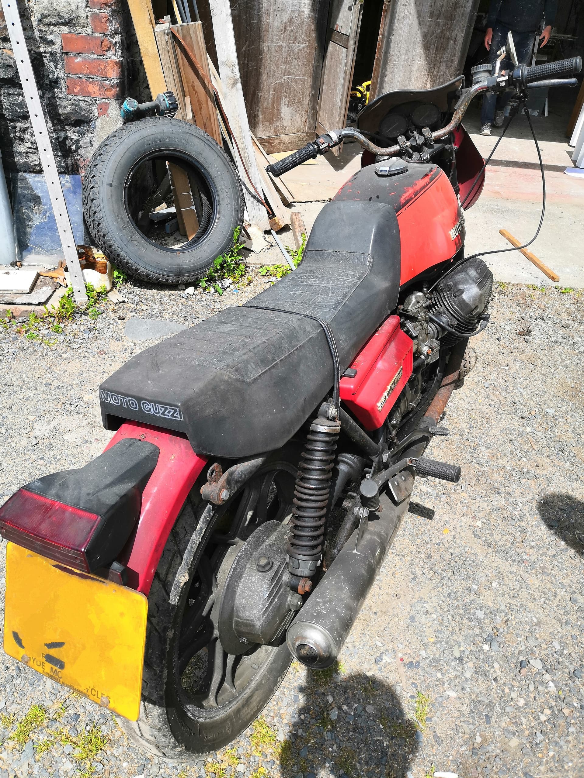
Nice to see I am not alone in my restoration task. My find was in relatively good condition, with the outer shiny parts all in excellent condition.
I am interested in the vapour blasting process on the casings - was this done with the engine assembled and on the frame, assembled and out of the frame, or bare stripped down casings ?
For now I have used Turtle Wax alloy wheel cleaner which has helped, but nowhere near a 100% new finish.
I did have the sump tray off at the weekend and the engine interior is immaculate, so I am loathe to strip the engine just to clean it.
Many of the parts have gone through the ultrasonic cleaner, including the rocker covers. I have also given these a thorough scrub with wire wool and a mild solution of phosphoric acid, but have left some of the aged patina on. My Daughter has coloured the Moto Guzzi engravings with red nail varnish and lacquer, which makes these really stand out.
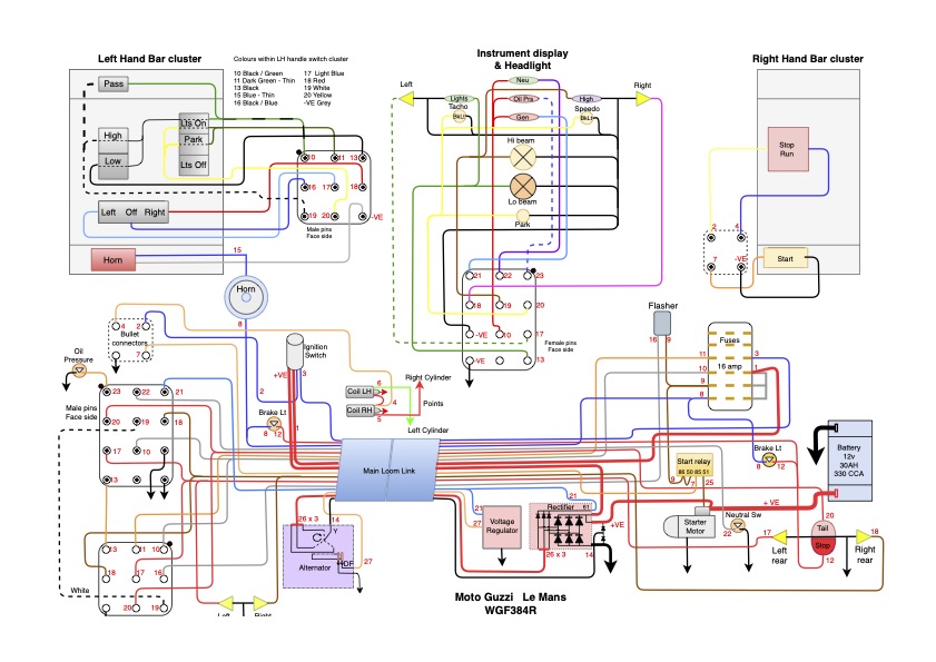
I have re-wired the whole bike. I numbered all the cables and did not follow the colour code. Final diagram attached.
I see yours is the later batch 2 Mk 1 with the dual bulb tail-light. As part of my refit I have replaced all the bulbs with LEDs, including thise in the instrument head - I would rather be seen on the road than have everything done purist style. If you do go down the LED route you will need a 68 ohm 2 w resistor to provide a ballast load to have the alternator excite. However, when I first started the engine in earnest last Sunday I did confirm the alternator does properly excite, albeit not until ~ 2800 rpm. The ballast resistor is omitted form my diagram but hooks in between fuse to cable 10 and cable 21 to the rectifier.
If you need to replace the original Bosch rectifier the Lucas I used to replace what I found already fitted was just £13.
My spend so far including the ultrasonic parts cleaner, new brake seal kits throughout and a host of minor parts is ~ £1,100 including the Newtronic electronic ignition. No professional fees as I am doing all myself.
This will be a great help with my electrical rewire. Many of the wires were melted on my bike. Thank you.
The engine casings were sent separately for vapour blasting. It was all done by Stephen Smethurst in Salford. A very professional job. You could try to contact him to see what he can do with the engine fully assembled.
Its a bit of a distance as I live near Southampton, but thanks.
Please note the japanese left hand cluster. I would strongly recommend finding a suitable cluster - the original Italian ones were rubbish. I found a new right hand starter and coil supply / engine cut out on eBay for a few quid. Ebay 395818356141
I bought all the accessory parts for the re-wire on EBAY, with the wire itself recovered control panel cabling from one of our work projects. I would suggest using 1 - 1.5mm2 with heavier for the main power runs. I used 6mm2 for the power to the ignition and rectifier, with 16mm2 on the battery feeds.
Halford offer a decent 35Ah 300 CCA battery for ~ £55 and it easily fits the space.
I would add I wire up complex electronic control panels for part of my day job, so for me and with just 28 cables this was quite simple, although getting all the lengths cut to the ideal length, and none too tight anywhere did take me a few days. I used mostly AMP folded crimps with a few coloured crimps where absolutely necessary and a few bullets, again where necessary, where I also used heat shrink to strengthen the crimps. I ran the new main loom through some PVC tubing, and used cloth loom tape for all the other exposed wiring. This goes on a lot neater than PVC insulation tape, and is not so sensitive to cold temperatures.
If you would like a standard wiring diagram I can send you an A3 copy of my own drawing click here or there are free ones on the internet by Carl Allison. Please note that Carl Allison’s diagrams do have some colour issues and if you would like a print for the workshop they need to be printed at A2.
Best wishes Chris
Oh, yes. I am in Bristol. I boxed up the casings and risked the post. £30 each way roughly. But a whole engine would probably be unviable
The Carl Allison does have at least one error - the headlamp control relay circuit just does not work and the relay shown was entirely absent. However, using LEDs and 1.5mm2 wire obviates the need for a headlamp relay anyway. The diagram of the left handlebar switch cluster is simply a load of indistinguishable lines that do not explain how the switch works. it took me a while with a multimeter to work out the LH Japanese Switch cluster’s operation.
My diagram is how I wired it and cuts out some double backs in the original diagram between the multi plugs. My version does work on all the circuits. I was also careful only to have two cables at the battery, as this simplifies clutter on the battery top and minimise cable disturbance when routinely removing the battery. The key when following the lines is the cable number marking at each end.
I agree but there is also the issue of colours where Bi (bianco) is sometimes shown as blue and vis versa. I have taken my own diagrams from the factory workshop manuals and so I am very confident that they are correct.
The left hand switches are like this on the original bike
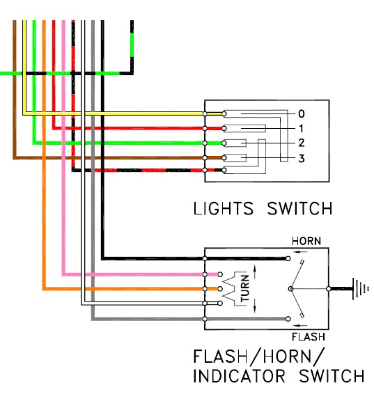
Lights
0 - off
1 - Park
2 - Dip
3 - Main beam
I know that many people ditched the original switch gear as it is fiddly and delicate, but if you tried to buy a set now, you would be looking at £150 per side and that is for tatty ones!
see here It depends on the level of originality you want to achieve!
Best of luck!
The upper light switch wiring sketch is still about as clear as mud. For me I am not that purist !
The numbers 0 - 4 indicate the position of the switch,
At position 0 no contact is made between any wires.
At position 1 the red wire and the yellow wire are connected, the red wire is live when the ignition switch is in the park position, the yellow wire feeds the parking light in the headlight, clocks lights and the rear light.
At position 2 the black/red, green and yellow wires are connected, the black/red wire is live when the ignition switch is in the run position the green wire is the dip and the yellow the rear light etc.
At position 3 black/red, brown and yellow wires are connected, all the same as position 2 but the brown wire is the main beam.
I hope this helps.
I’ve used the lefthand switch cluster from a Suzuki GT550/750 from the 70s, I stripped off the black paint to a polished aluminium finish. It looks very period, much better looking than the original and has functioned perfectly for 20 years. The right side switch is trickier to find a suitable looking replacement.
I use the original right hand switch as standard, but as I do not have indicators on my bike I use the indicator switch as lights - off, dip, main. I indicate with my arms! ![]()
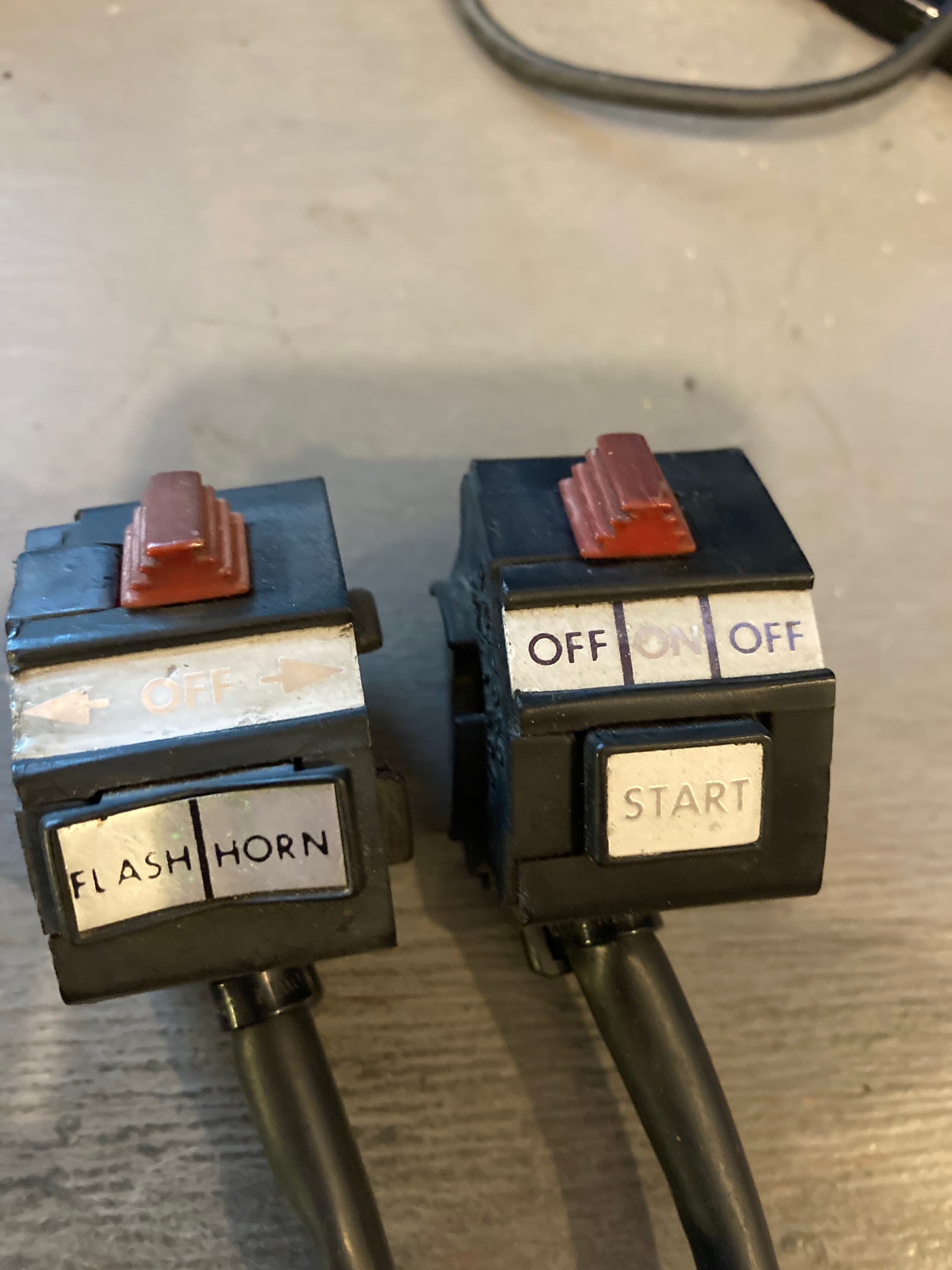
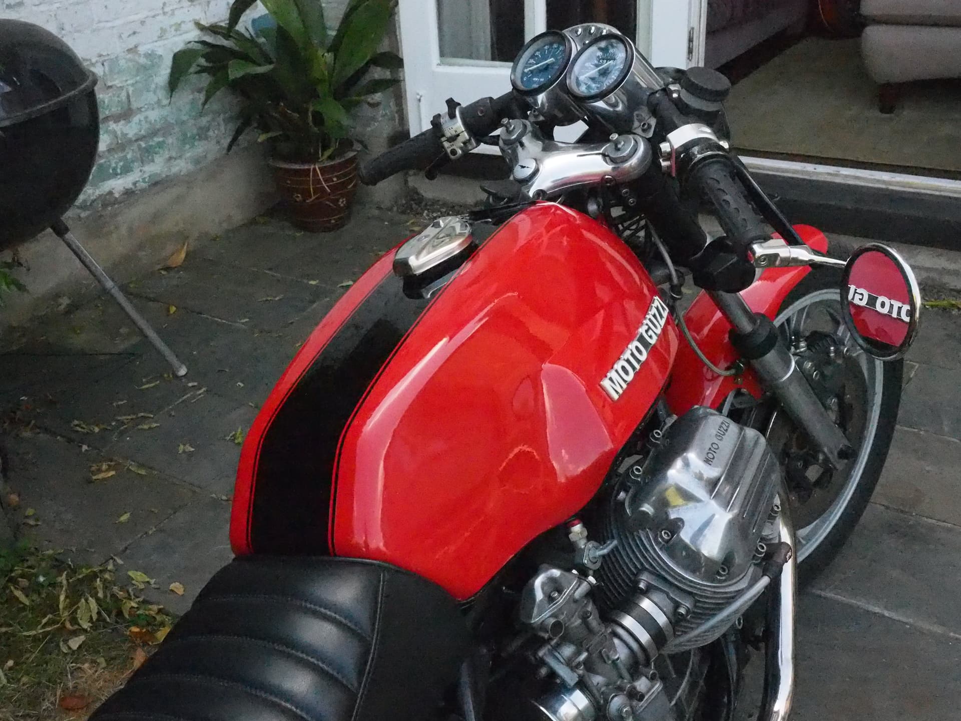
Interesting solution! Here’s a photo of the Suzuki cluster on my LM1. You can also see the solution I found for the right hand. I think this is what they call a restomod.
Lovely looking bike. I like the paint scheme. No nose fairing though? The switches don’t spoil it at all, and I like the bar end mirrors.
Sensible mods.
Glad you like the paint scheme, I’m aiming to reveal more of a '60s style cafe racer so have discarded the fairing. I believe there are some areas of the original machine that can be improved on visually and functionally. I guess you will have to choose how much to reinstate of the original.
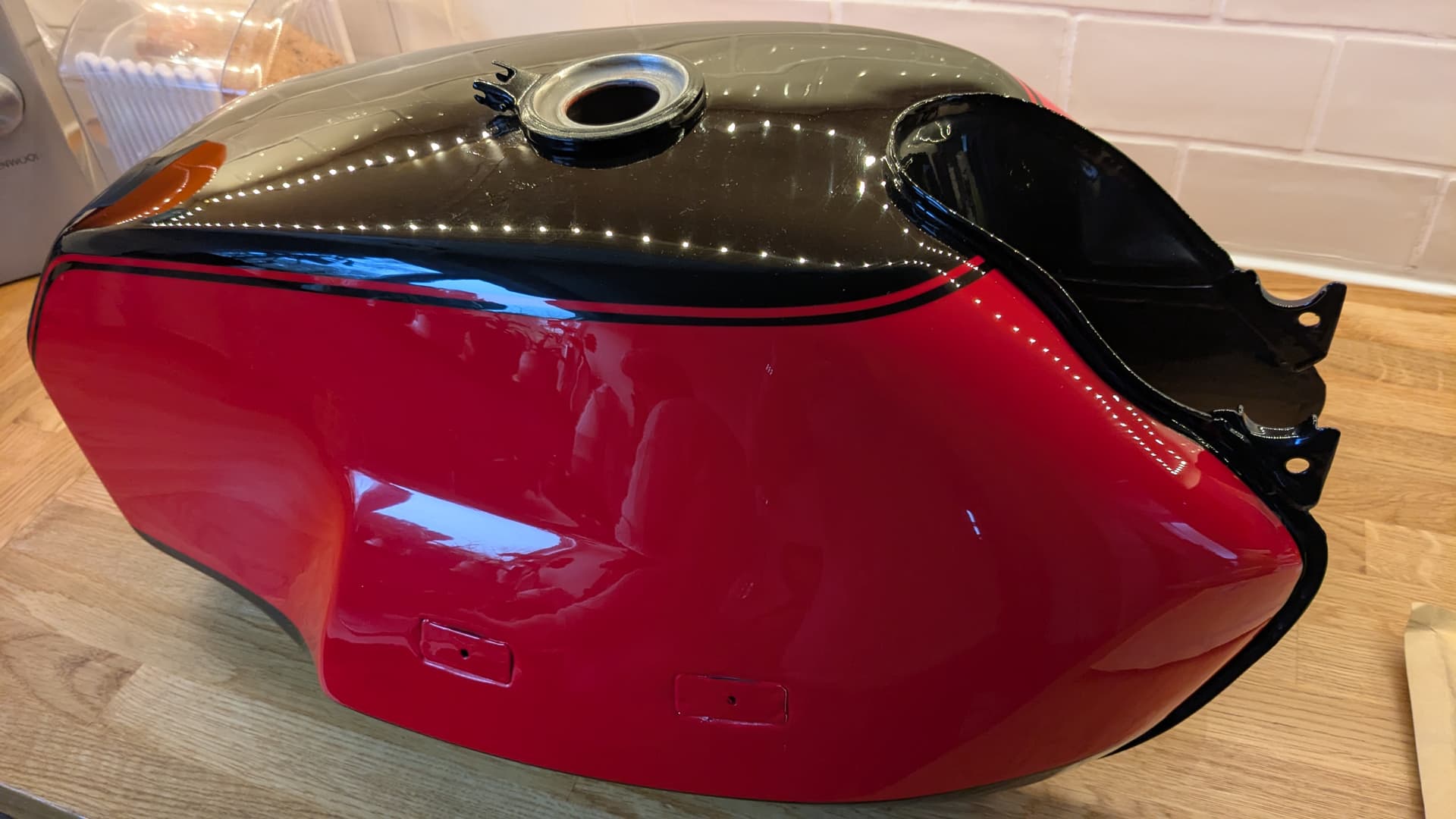
A thing of beauty! I agree the gloss black is better than the satin. Also the black boundary following the lower seam along the bottom of the knee indent is a good improvement over the original, returning to the original V7 lines.