![]() not a bad idea , just priced one up from gutsi bits
not a bad idea , just priced one up from gutsi bits
1 Like
I have the exact same problem, just havent got around to looking at it. Other than swapping all the relays. When i do I’ll do the side stand first then the ignition switch. The bike was running fine on way to Guzzifest and then just cut out as if it run out of fuel. BTW replaced the fuel pump, but no difference. So i will watch this with interest for ideas
Did the bike recover or is it still dead?
Reason I ask is that mine did something similar last month at the VMCC East Kent run. It started after 5 mins but then it had another couple of episodes and the only thing we could see at the time was some corrosion on the battery terminal but cleaning this didn’t fix it I had to wait about 20 mins and then it would start. Going through all the stuff Chris has listed above but nothing obvious and it hasn’t cut out since. I hate intermittant problems!
Still dead. Im a bit busy with work so ive not really got going yet, this started cutting out when hot, then once cold would start again. Then it lost the spark completely but was still turning over ,eventually gave up altogether, it was a slow painful death ![]() …week off week after next when ill knuckle down and try and sort it. Ill keep you posted
…week off week after next when ill knuckle down and try and sort it. Ill keep you posted
This is typical symptoms for a Crank Sensor!
Thanks nik but That was actually the first thing that was suggested to me when all this started, and was the first thing i replaced. Sadly to no avail. Ive changed the reg/rec , even tried a different ecu
You may find this useful ![]()
For sensor values if nothing else
I’m assuming you are aware that there are 2 sensors tied to the timing, one on the flywheel in the bell housing and the other on the cam wheel at the front of the engine, items 7 (rpm) & 8 (timing) in the drawings
efiman.pdf (1.9 MB)
1 Like
A friend of mine had a similar problem with his Cali 3, we got Andrew Pierce (Baldric article) to take a look, as he is good on electrickery, he discovered it was the Molex connector block just behind and below the battery, it was suffering badly with verdegre. It’s in a very vulnerable position but is easily ignored.
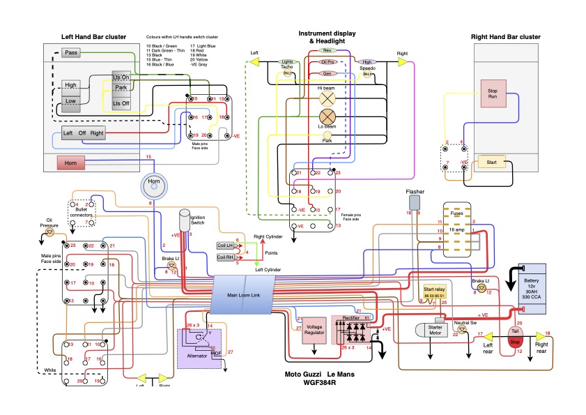
A full re-wire was amongst the first of the jobs to tackle upon my recently acquired 1976 Le Mans 1. Initially I tried to follow the original wiring diagram, but found variations and at least one circuit that simply does not work (headlamp relay circuit). Plus a non original Lucas rectifier without the star point connection to the stator.
So I traced each circuit individually and then numbered each circuit and gave it a label.
The original LH switch cluster had been replaced with a (better!) Japanese version so I spent several hours working out what the 10 wires into it did. I then added this in block form over the top of the original and indiscernible switch cluster upon the diagram.
I then realised that with al the cables numbered it was simpler to produce the entire diagram in a series of blocks: Main Loom; LH cluster; (new) RH cluster; Instruments and Headlight; Ignition.
The wiring is now virtually finished and everything so far has worked first time. Just finishing off the 5 wires to the rear seat and waiting for eBay delivery of an extra 6 block connector to make seat removal simpler.
I have also run in loads of -VE connections to the frame, as there is nothing like a poor neg return to annoy on a run out. The battery now has only two connections, with the ancillary power connecting from the main =VE cable at the starter motor connection.
The majority of the cable end connectors are the AMP folded style, although I have used a few Red/Blue/Yellow crimps where necessary, and all of these are reinforced with a heatshrink sleeve. Once the loom was assembled I have wrapped each leg in cloth loom binding tape, including single cables.
All the lights are Canbus compatible LEDs, which means the Gen lamp should work to excite the alternator and the indicators should place sufficient load to make the flasher relay work, but if not a couple of ballast resistors will sort that out.
I have discovered the original Bosch Rectifier, which includes the Star Point diode pair, is still available from Gutsibits, so I am considering whether I buy one at £95.
The electrics re-wire has cost me ~ £40 so far although I do have access to loads of decent coloured wire at my work, but with the number labelling of each cable at each end and junction I have considerably deviated from the original colour scheme.
“The electric re-wire has cost me £40”…
I’d suggest it’s more like “£40… and a lifetime’s experience/ skill.!”
Nice job ![]()
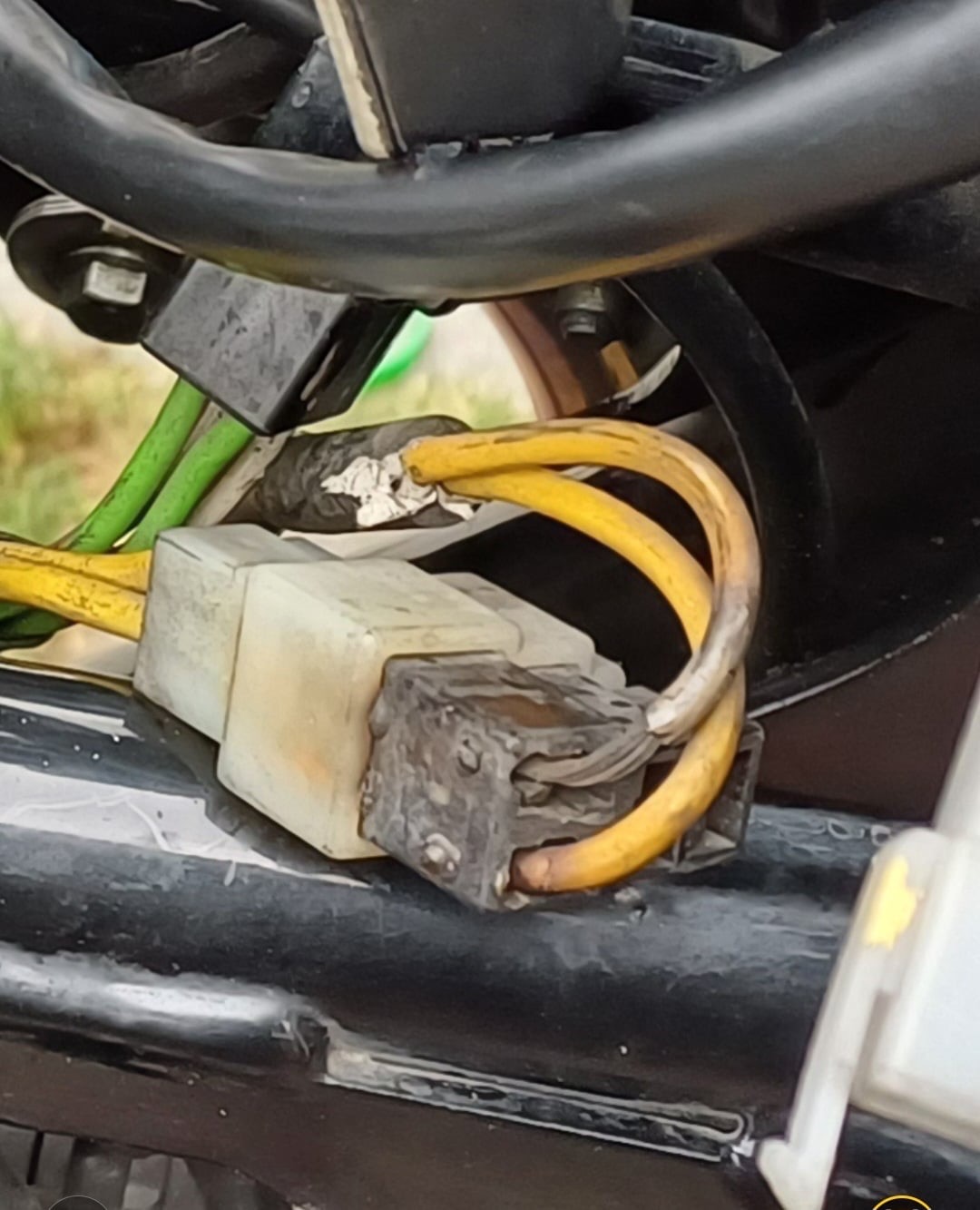
Whilst I’m no leccy hexspurt, I’d highly recommend a deep dive to check all connectors, the pic shows the burnt wiring on the alternator- reg/rec connector block of my V7.
When mine failed to run I tried all sorts to get it to fire up, including fixing the melted connector, checking/cleaning/testing the clutch/sidestand/kill & ignition switches, and although the battery seemed good, and was holding a charge /powering stuff up, it turned out a replacement was all I needed in the end.
After a period sat unused by the previous owner, it simply didn’t have enough ‘umph’ to crank the bike over any more.
Is your battery definitely good.?
I omitted to disclose I routinely re-design and re-wire industrial Water Chiller control panels for my day job. These routinely have ~ 200 - 300 individual cables - the Le Mans has ~ 28 individual cables. The trick for this one was getting all the ends in the right place relative to mating cables, and indeed the re-wire has taken me longer than the normal panels I re-wire, plus days on DrawIO doing and amending the diagram.
If anyone wants to try creating a schematic just enter DrawIO into your internet search bar - free and excellent.
1 Like
Interested to see you used canbus led for gen lamp. Does this pull enough current (3W)?
I wired a 68ohm resistor in parallel to do this.
I have yet to test the generator as I have not yet started the engine. I worked out I needed ~ 70 ohms. The original bulb is ~ 2w. The new bulb is about 0.2w.
W=I V or I = W / V 2/12 So the current draw should be ~0.17 amps
V=I R and R = V / I so the resistance needs to be pulled 12 / 0.17 = ~70ohms
The resistance of the new LED is negligible, so a 68ohm would be about right, but I am hoping the canbus satisfying inbuilt resistor will work. I will measure the actual current flow as I expect anything less than 0.15 amps would likely be insufficient to excite the rotor field, but at the same time I do not want to put too much power through the rotor field.
I will return to the thread to let the end result be known, but might be some weeks away from an engine start yet.
I have looked closely at the overheated connector block in the picture and that looks to me simply due to dirty contacts in the connector. These are spade type.
I am using Tyco connectors, as used for the 12 & 15 pin connectors on the original loom. These can be bought from Ebay for a few quid including new pins, but also needed is an AMP folding type crimp tool. A folded crimp is far stronger and longer lasting then the ‘Red / Blue / Yellow squeeze tight’ crimps as these are not so good especially if the cable cores do not fully fill the crimp hole they reside in.