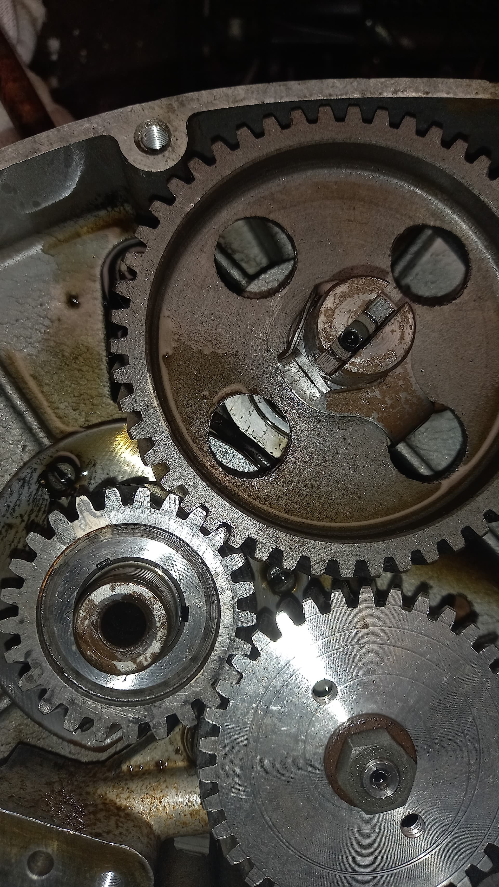
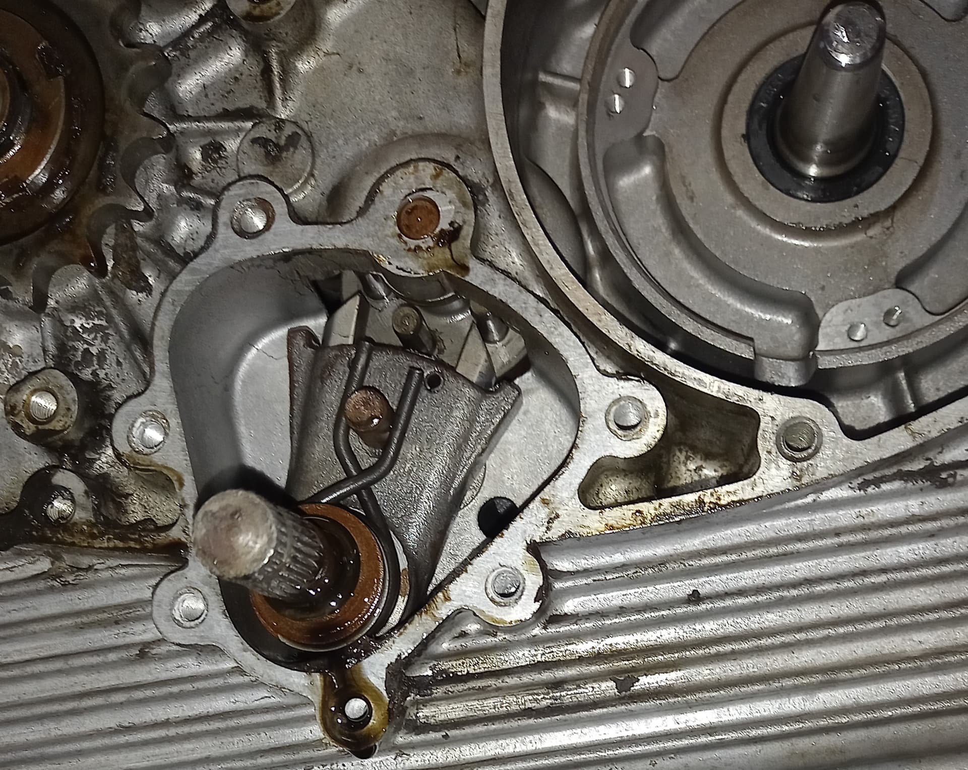
Hi there, 1971 stornello 125 ,5 speed.Need to strip out and replace/repair crank. I am am bit confused with can timing marks, With piston top dead centre the marks are not lining up, ( beige paint?) Or am I missing something? This is as found not removed anything yet bar the nut.
Are you on the compression stroke or the exhaust one?
The larger cam gear will rotate at half the speed of the smaller crank gear. There should be small paint marks on the gears. Another thing to be aware of is that there are 3 keyway slots in the smaller crank gear.
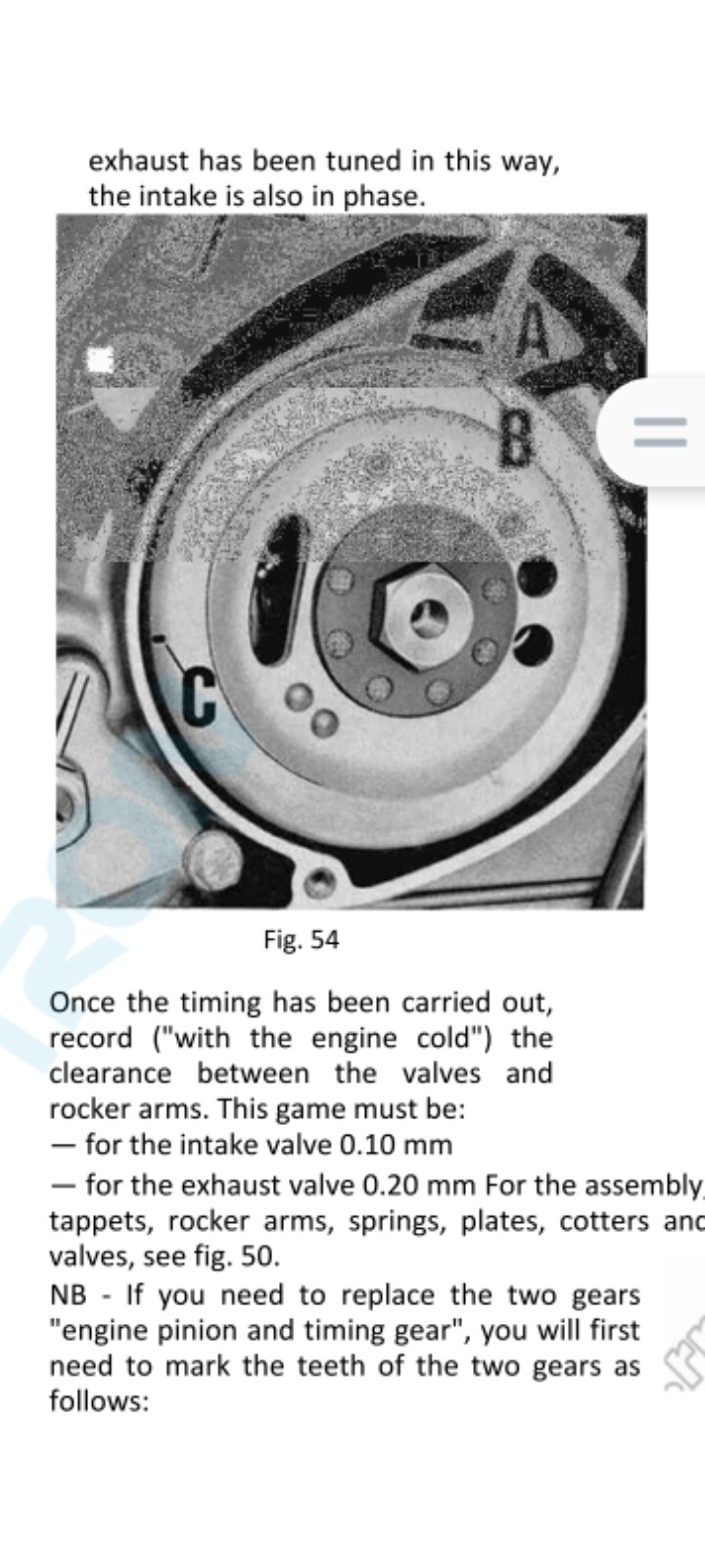
If it does all goes wrong, the manual should give you the details on how to retime the valves by measuring around the flywheel to determine the point where one of the valves is just starting to open.
Thanks Don ,didn’t want to take apart without checking, The “manual “ is difficult to work with ,my Italian in nonexistent, I read it as, timing marks line up when magneto flywheel is turned 120mm passed TDC.
I’m pretty sure it is that you assemble it so the marks line up and check it by measuring around the flywheel at which point one of the valves should just be starting to open.
If possible, mark the crank gear to the crank shaft as well as the relative positions of the 2 gears.
If you have Google translate on your phone, you can translate blocks of text using the camera option. Do you have the English service notes for the 4 speed Stornellos?
That should help you, things haven’t changed that much between the 2 versions.
1 Like
downloaded the English version thanks. There is a bit of beige paint on gear wheels , acording to book page 48/49, they should line up when flywheel is rotated to “C” past TDC firing stroke ,But they don’t line up on mine. So not sure if paint is in wrong place. I know this motor has previously run, and I have not disturbed the the gear positions ,but I will have to ,to get crank out. Think I will have to mark and photo everything as is , and worry about it later when rebuilding.
Stripping the motor down should be pretty simple.
When rebuilding, the gearbox does need to be set correctly with regards the selector mechanism. Those service sheets explains the process on a 4 speed engine, I’m not sure how it converts to a 5 speed engine. I would suggest a bit of translation of the manual may be needed.
I don’t know if this is relevant but my Ducati single has timing gears with tooth numbers such that the dots only line up every few rotations of the engine i.e. at TDC but not every time it’s at TDC.
Thanks Ranton, Normaly they line up on firing stroke. Reading further into manual,I find there is two “C” marks. The first c is 120mm anticlockwise from TDC , exhaust valve just starting to open .Then I find another C clockwise from TDC, the book states this is where the timing marks on crank and cam line up.Not sure if C is a miss print as my engine lines up about F. But I cannot find a measurement for D,E, or F. nor do I know what these marks represent.
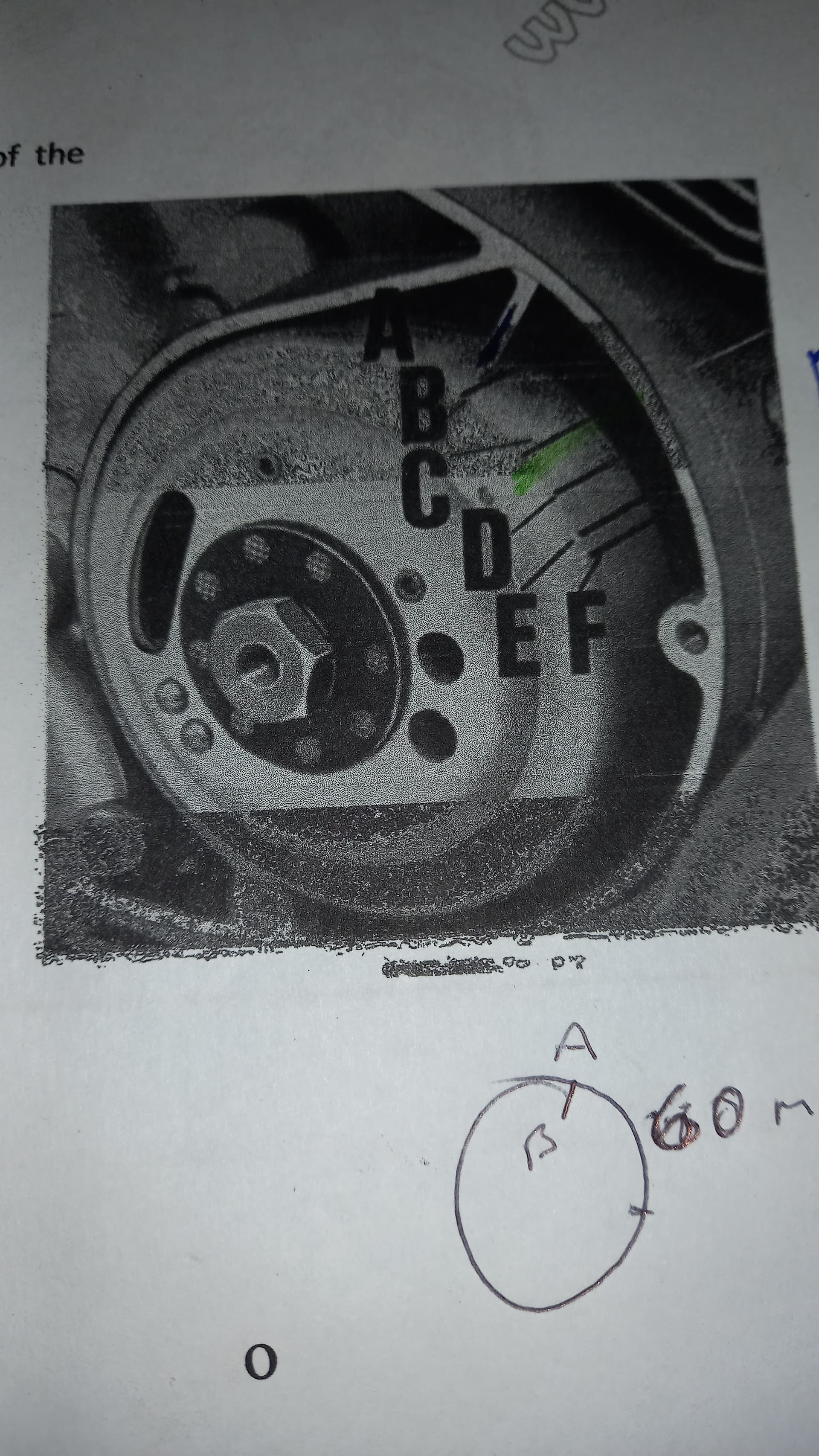
Anyway I am going with Mark F and continuing with strip down
Oooh, have you got an english translation of the workshop manual? I would love a copy if you have one.
Irs not the easiest thing to read and bits are missing .I downloaded it, can’t remember where from. I see if I can find it again,
I’ve not drawn a wiring diagram for the Stornello yet, but I guess they are relatively straight forward?
![]()
Hello Donald
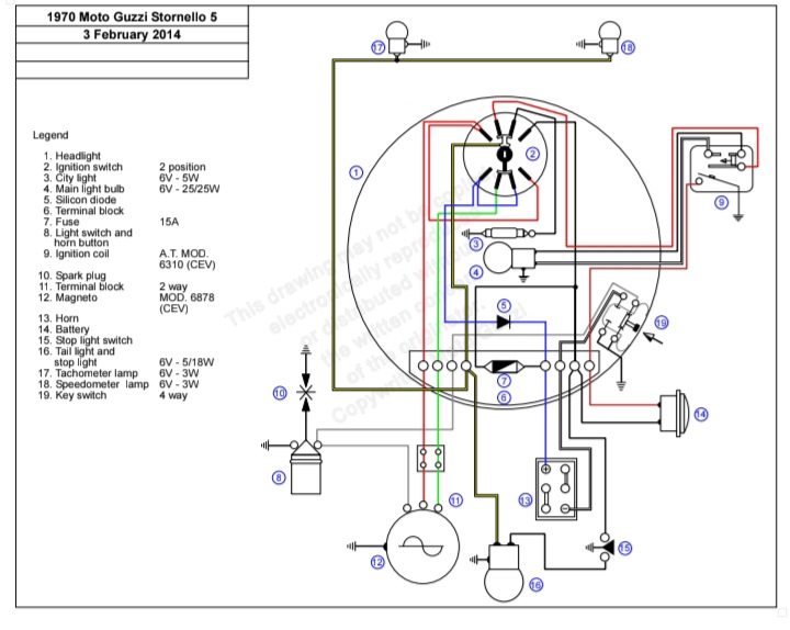
This looks like Carl Allison’s wiring diagram, they are generally very good but I’m often a little wary as some of the colours are sometimes incorrect.
On this he has labeled the light switch and horn button as number 9 which on the legend as the ignition coil and visa versa.
The connector block number 6 has a different layout to the one in the workshop manual I have found on the Guzzitech website (see here) which also shows the key switch as the same item as the ignition switch but these have been separated on Carl Allison’s drawing.
The colour of the supply to the city light is shown as black whereas the manual shows this as yellow.
I am also not convinced that the key switch can be 4 way and the ignition switch 2 way as I assume that the combined switch does all functions.
As I said above I am always a little wary.
Best wishes Chris
Yes Chris, you are correct there are some errors, I never checked the Legend, the harness in the box of bits that my stornello came in matched that diagram except for the yellow park light wire. The key when pushed in , is ignition off / on, and when pushed inn and turned one gets head / tail lights,when turned other way parking light .
There are a few different versions of the Stornello electical systems.
The image above is for the later 1970 to 74 5 speed bikes, there are 3 different versions for the earlier 4 speed bikes. A CEV version, a Marelli one and the 68 to 69 4 speed 160 which had a completely different electrical system. Page 139 & 236 in the link above shows the CEV system for the 4 speed bikes. The manual gives 2 different diagrams for the later 5 speed bikes, the road version and the Scrambler on pages 328 & 329.
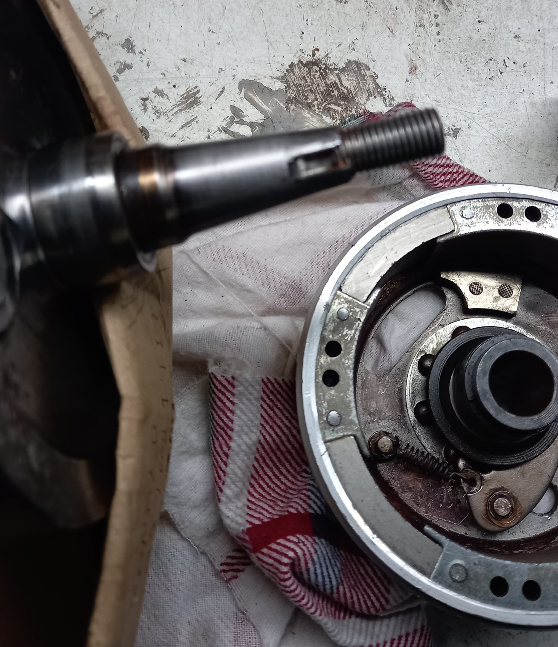
A quick update, engine striped, crank out and repaired. Just have to remeber how it all goes back together.

1 Like
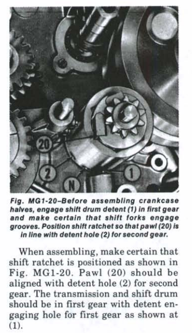
That looks like a good job. The one thing to watch out when rebuilding the engine is to set up the gear selector mechanism correctly or you won’t get all 5 gears. This is the instructions for the 4 speed engines. Your’s will be slightly different as it is a 5 speed version.
Yes thanks for that, the 5 speed has a claw type lever acting on 4 pegs.. I put it in 1st gear when dismantled and took few pictures .
Making gaskets at the moment
1 Like
Well finally got engine back together, Started on 3rd kick, Just got gear lever and cover to mount .Too dark cold and wet so the test ride will hopefully be tomorrow.
1 Like