Following advice on an earlier thread I am looking at fitting the Newtronic electronic ignition system to my Le Mans.
Having thoroughly read the install instructions and also the Guzzi workshop Manual there is a distinct difference over which cylinder to time first. Obviously this is the one controlled by the distributor body position, but in the Guzzi Manual it states very clearly RH first (Red lead), but in Newtronic it states LH first.
Guzzi Manual Instructions
3 The ignition timing for the right-hand cylinder should be checked first.
Newtronic instructions
NOTE: The design of the Newtronic system means that the manufacturers timing procedure should not be used. Initial position must be set on the LH cylinder with the final adjustment carried out on the RH cylinder.
Assuming the above text has the cylinders reversed in regard to the cylinder adjusted by the distributor body, which clearly must be the cylinder timed first, am I right to assume the critical difference eluded to in the Newtronic is that the Guzzi manual instructs only for static timing, whereas the Newtronic instructs for dynamic timing at 5,000 RPM
Notably the colour references for both Guzzi and Newtronic concur - RH is the Red wire, LH is the Green wire.
Can someone confirm it is the RH first please, or if the Newtronic instructions are correct can someone please explain why.
Its been a while since I’ve done this but I would follow the Newtronic instructions.
I think the optical pickups are flipped. The dizzy has to be timed first which means LH with Newtronic and then the moveable base plate RH.
It should be apparent when timing that its correct.
Notes
Disconnect coils while timing as you can blow the power transistors in the Newtronic unit.
If you have the later Newtronic unit it has static timing lights.
If you have removed the dizzy make sure its not been refitted 180 degrees out (guess how I know this can be done)
If you have any doubts give Newtronic a call 02074034334, Ive found them to be very helpful in the past
Ive just fitted a Newtronic to my 850 T3 - the instructions are correct if a little confusing on first read.
Time the fixed pickup first - which is the left cylinder. This should be the upper fixed pickup on the distributor. Once this is correct lock off the distributor body with the clamp and then time the adjustable pickup for the right cylinder on the adjustable plate. You may find as I did, that there isnt enough adjustment for the right cylinder on the first attempt. I had to push the fixed LH pickup as far clockwise as possible and the push the adjustable RH pickup as far anticlockwise on their mounting holes, then start the process again to get it correct.
As per Mr P note - make sure that the timing isnt set to fire on the exhaust stroke - easiest way to do this is - get the LH cylinder to TDC on the compression stroke and install the distributor while holding the ignition rotor in the LH cylinder firing position.
I hope this helps
The switch to electronic has made starting, tickover and general running much better, well worth the effort. Shouldnt need adjusting every 4000 miles either.
Time it on the fully retarded mark at 1000 rpm to get it close to correct (one tooth before TDC). Then do the 5000 rpm adjustment to get it correct at full advance. Mine was pretty well spot on straight away. It feels a bit brutal revving a T3/Le Mans etc to 5000 rpm in the garage so make sure its properly warmed up before you do the final adjustment. To do this properly you need the tank off and a temporary fuel supply to the carbs.
There are LED’s on the Newtronic unit so it can be timed static to get you close initially. I cant remember for sure but I think the unit fires when the LED goes off.
The top plate is fixed and this is the left cylinder and moves with the distributor body, the lower one is for the right cylinder and is adjustable on the back plate.
Make sure the black plastic disc is fully seated over the cam so it passes through the gaps between the lights. I had one that hadn’t gone down fully and was damaged when the motor turned over.
That looks interesting. How does the rotor lock onto the spindle so it can be adjusted? The ususl plastic one is just a very tight fit when pushed down.
Grub screw. Thats the fiddly bit, making sure the rotor doesnt turn when tightened. Plus a little movement is a big angle on such a small diameter. But even so its easier than moving the distributor.
And, as been said before, once you’ve set it you can forget it.
My friend has a Yamaha with some kind of electronic ignition where a grubscrew keeps the rotor in place. I don’t know if he didn’t tighten it properly but it fell out and stopped the bike on a VMCC run.
It fell out when we took the cover off but miraculously we found it and tightened it enough with the tip of a penknife to get him home. No-one had a small enough Allen key.
Done 2000 miles or so, including a trip to Mandello, no probs.
However it does raise the point that when setting up theres a fine line of tightening enough and overtightening which may leave an indent which makes it impossible to adjust by a fine degree.
I just nipped it up and re hecked then nipped it up a bit more until I was happy.
Oh, and I did take the plastic rotor to Italy along with a second Newtronic unit, just in case!
I have Newtronic units on both my Guzzis now, my Spada 1 came fitted with Pirhana (Newtronic) when I bought it, and I just fitted a Newtronic to my T3. It just works properly and in theory shouldnt need adjusting again once correct.
For anyone still running points I have a brand new boxed set in the “parts for sale” section of the forum
This looks a far better rotor lock arrangement, and for ~ £30 seems a bargain.
Also the current price including delivery for the CKT-MG1 Newtroinc kit is £171 inc VAT & delivery as the website pricing is out of date. Mine should arrive tomorrow, but will likely now wait for the new metal rotor. Indeed once I have seen the rotor I might simply make one from aluminium bar stock. Looks simple enough to machine one.
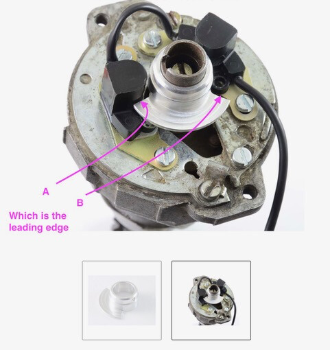
Which is the leading edge of the rotor that generates the spark impulse ?
I can also see the arrangement of the contact lights is different to the original contact breakers set up, so hence the difference in which cylinder first.
I think the pickups in your picture (from the HMB website) are fitted the wrong way round, the pickup at the end of the wire should be on the adjustable points plate. See item 6 in the Newtronic fitting instructions - Thats certainly the way mine are arranged.
I’m pretty sure the system fires when the beam is remade rather than broken by the leading edge. The leading edge is “A” in your picture - the rotor goes clockwise. The spark is triggered when trailing edge “B” is leaving each of the optical pickups and the beam gets remade.
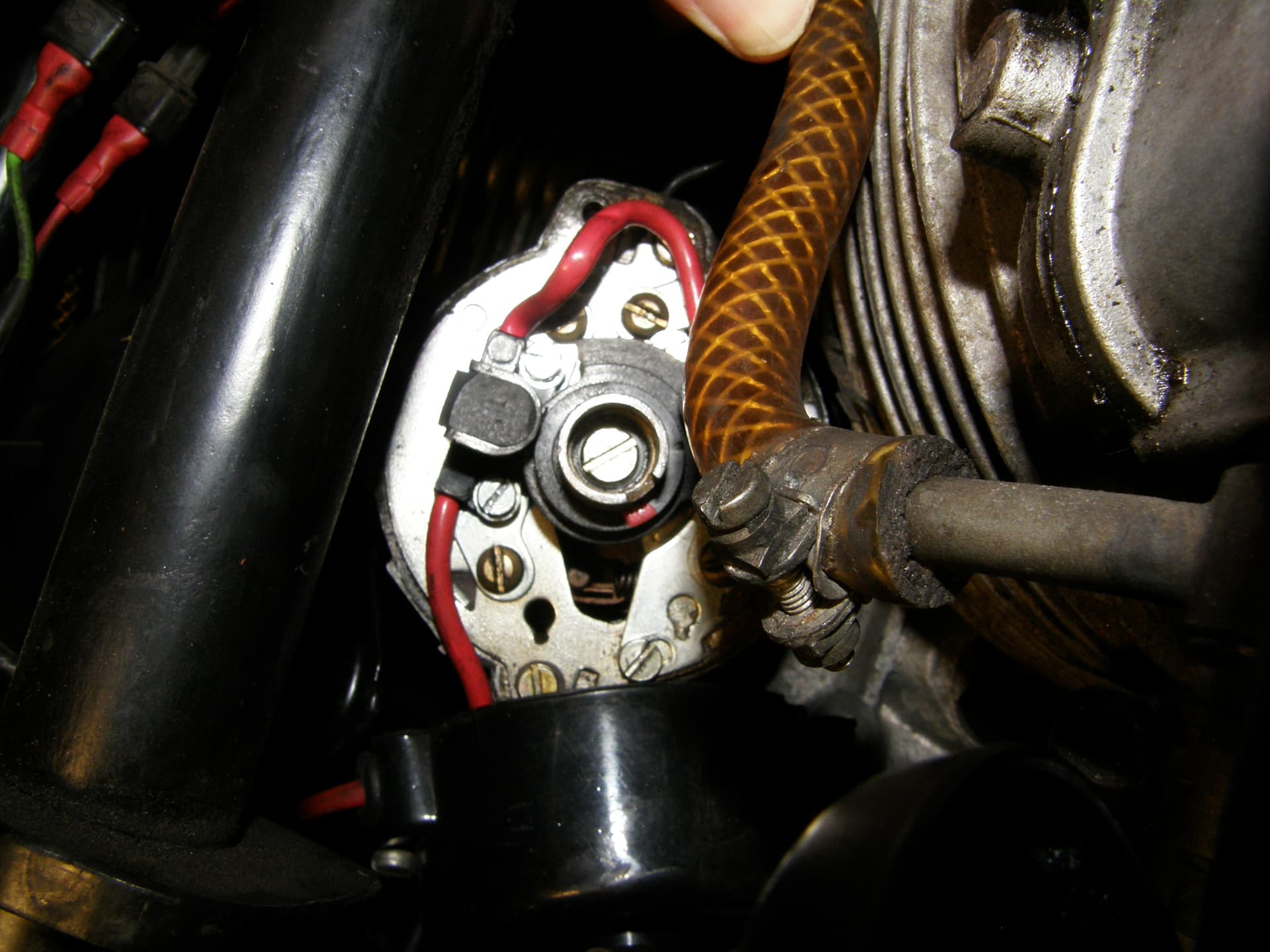
Thanks Russell. The instructions mention the cable exiting towards the front of the bike, which in the photo is the nearest side - the cable notch is at the closest edge.
I intend to use some aluminium bar stock to make a rotor using the supplied plastic one as a template. Should be simple enough to machine this up. I am fortunate to own a Chesterfield lathe mill, and a reasonable set of tooling to match. The cut away would be simplest with a dividing head, but without I can simply machine the cut out with the mill arm over the locked lathe chuck. The trailing edge profile will be critical then.
I will likely fit two locking grub screws - belt & braces.
The parts are now here for the set to work of the ignition so that is the plan for the weekend. The Newtronic is expected tomorrow or Friday.
I was wondering, if you are going to make the rotor, could get away with an interference fit with a slot. There by doing away with the grub screw and rely on the friction to hold it. It would be easier to set up. Bearing in mind the original plastic rotor is held by friction.