V50 II Ignition timing

I think I may be opening a can of worms here. The V50 II has Bosch electronic ignition which looks well engineered in typical Bosch fashion. However it doesn’t seem to work well in respect of the advance curve. But I’m already getting ahead of myself.

The manual says that there are two marks on the flywheel “D” and “S” for the right and left tdc positions and also two marks indicating max advance for the two cylinders. None of those marks are present on my flywheel. So, I found tdc for each cylinder with a dial gauge through the plug hole and marked the flywheel with a paint pen. I then counted 4 degrees per tooth on the ring gear and marked 34 deg btdc for each cylinder. Please shoot me down if I’ve got any of this wrong, I’m new to this engine and I am going by the information I manage to glean here and there!

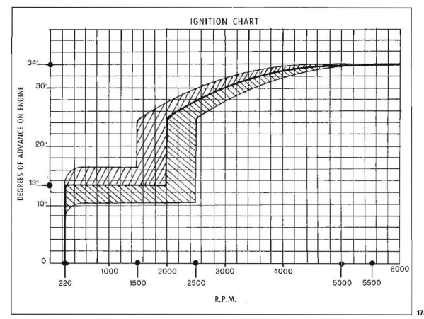
I now put the strobe on it and I found that at idle, the timing was around 10 deg btdc, which sounds OK to me. As I increased the revs, there was no advance until I reached about 2500rpm, when it suddenly jumped to about 25 deg btdc, causing the engine revs to shoot up. It’s not easy to check what happens after this, but the timing actually retarded slightly before advancing again (more smoothly) up to max at around 3500rpm. The max was different on the two cylinders by a few degrees.

On the road, this means that the bike either surges forwards or dies a death at about 2500 rpm. It can feel like a huge flat spot as you accelerate. It can also be a pain in the neck if you are doing a U-turn.

The diagram in the manual indicates that this is correct for this ignition and if I’m reading it correctly, there is quite a wide “tolerance band” - mine was towards one end of this band. I gather that the change to points ignition on the V50 III was to cure this problem (?)

I have found two after-market electronic systems on the internet from Sachse and “Silent Hektik” - both located in Germany. Both look good and both are eye-wateringly expensive. They both come with multiple advance curves, switchable and one (Silent Hektik I think) is programmable. In both cases it should be possible to select a curve which is a big improvement on the original Bosch system.

Another consideration is that apart from any shortcomings in the advance curve, the Bosch system is almost 40 years old. I’m not sure that I’d trust it for touring abroad unless I was carrying a spare. Spares do appear on ebay, but at silly prices for a second hand bit of 40 year old electronics!

So, has anyone any experience of the Sachse or Silent Hektik system? Any other comments gratefully received!

That sounds pretty much like what it’s supposed to do. The electronic ignition does have a very steep (almost vertical) advance curve. Some bikes seem almost oblivious; others are badly affected.

Do you have a copy of the workshop manual (downloadable from various places)?

This is the relevant diagram:

I have wondered myself whether something like a Boyer could be substituted (obviously it would need one unit per cylinder) as essentially they don’t have to do an awful lot. Or even for those of us with the skills, an Arduino or Raspberry custom-made unit?

I have a Silent Hektik system on my Mk3. Yes it was expensive, I got it from TLM, but it’s the best. The bike starts and runs with no problem. I did a lot of research before I bought and I believe this system is better made. It’s been on the bike 18months(over 5000m) and never missed a beat.
I can PM some photos if req.
Steve.

Steve,

Many thanks for that. I would appreciate some photos if you have the time. Currently I don’t think there is anything actually wrong with the old Bosch system and I dare say I would get used to the advance issue, but reliability is also a factor and the Bosch units are looking very tired due to age. I like the bike and I want to use it but it needs to be reasonably dependable. I am certainly not spending significant money on another 40 year old unit. Typical ebay price is about £70 plus £15 post.

Looking at the German websites, I did like the look of Silent Hektik, especially as their kit includes new coils. I am also looking at the Sachse system for my 500 Morini. In that case the original system works fine (made by Ducatti) but again, it is 40+ years old and they are a bit prone to failure now. I don’t think SH make a system for the Morini - probably a bit of a small market!

Thanks again for your comments,

Joe.

Thanks!

I do have the manual and I have been looking at that graph. I have actually given some thought to modifying a Boyer system, I may have one kicking about somewhere. The max advance is 38 deg to suit Triumph/BSA/Norton twins. Problem is that it’s designed for camshaft trigger which would be very tricky on the Guzzi. If crank triggered, both plugs would fire every revolution which wouldn’t matter I don’t think, except that the trigger speed may be too fast for the Boyer at high revs… Hmm, something to think about. That would be a very cheap option, just needing a modification to the trigger/pickup for 90 degree twin instead of 180 deg. No doubt there would be some hassle mounting it. I wonder if anyone has tried this? I’ll go and have a root in the garage for a Boyer twin system.

Joe.

I’ve been running my V50 II from new with the OE ignition. It seemed pretty much OK from new, but decidedly worse after I disturbed the ign sensors when I swapped out the cam chain. As noted the advance ‘curve’ is very abrupt and apt to cause the flat spot, typically around 2.5k – 3 k revs where the action all takes place. What I was advised was that whilst on the one hand you can strobe and adjust each side to be accurate on full advance, if the trigger/sensor air gap differs between the two then the flat spot will be more pronounced. This is because it causes the two sides to go up that curve at slightly different engine speeds. Once I had reset, and it is a PITA to do, it was all pretty good again.

Some years later it seemed to be getting worse. This time I replaced all of the jets in the carbs – still all std, to take into account wear in there opening them out. This restored things pretty well.

So my view is that with everything set up about as good as it could be the flat spot is reduced to the point that it is quite acceptable.

Now this last year after the bike had been standing all summer I pulled it out for winter use and it would only fire up on one cylinder. Sparks only on one side. After some foolishness I tracked this to one of the ign boxes having failed – they sit back of the battery bay on each side of the bike. This is the first failure I’ve had on these since new in 1980 and over some 65k miles. The units are ‘potted’ and that epoxy or whatever has shrunk possibly allowing moisture in down the side of the case. I researched at that point and it seems that these self-same units were used across a broad range of Italian bikes back then, so maybe that advance curve worked better with some than with others. I also looked at the replacements you’ve mentioned at this point.

However, I picked up another (previously enjoyed) unit from a bloke on line called Paddy Ducati for £55. Plugged in and away we went. So I too am suspicious of further failures now in kit this old. My view is that if you can tune out the flat spot to your satisfaction then the cheapest way to go is buy another box as a spare and chuck it in your tool roll.

Meanwhile since swapping out the unit my flat spot seems to have returned with a vengeance. It has to be the same type of unit as it has the same Bosch code on the front so presumably the programming is the same. So … I’m going to try swapping out my ancient spark plugs for new as the next step.

Thanks for all this info. You have convinced me of the value of doing a careful set up on both pickups and synchronising the advance curves on the two cylinders. So that will be my next job. I’ll report back here in a few days, no playtime available this weekend! If I can make it satisfactory, I agree that the cheapest approach to reliability will be to pick up a unit on ebay or wherever and carry it as a spare.

My thinking was to use 2 Boyer black boxes, one for each side. As you will know, the Boyer system actually runs effectively at engine speed as there are 2 trigger coils at 180 degrees driven by the camshaft, giving an idle spark as the ignition coils are connected in series.

As I understand it, the advance is controlled merely by the fact that as the engine speeds up, the voltage provided by the trigger coils increases. So at low speed the lower voltage actually retards the spark, the retardation reducing as the speed and hence voltage increases. But I may have this entirely wrong.

I’m sure I’ve seen a schematic for the Boyer box somewhere on a Norton site so will have a look.

I missed a Bosch box on ebay a few months ago which ISTR went for £10 or so… As you say, nice to have a plug and play spare. When I used to do long continental tours on my Commando I carried a Boyer box with me just in case (never needed it, although did need to remake the connections on the backplate…)

I had a look in the garage and found two Boyer systems, one for a twin and one for a triple. The rotor for the twin looks like this:

This is normally fitted to the exhaust camshaft on (say) a Bonnie and rotates inside a stator which looks like this:

This side shows the two coils, set at 180 deg. The other side:

has two pole piece extensions which pick up the rotating field from the magnets on the rotor. Looking at how it’s connected, both coils trigger simultaneously, twice per camshaft rev or once per crankshaft rev. As you rightly say, the two ignition coils are connected in series and both fire every 360 degrees, so each plug has a wasted spark on the exhaust stroke as well as a good spark on the compression stroke. The CDI box is timed at max advance and then retards the spark according to rpm, with max retard at zero revs. The box looks like this:

Your idea of using two boyer boxes should work well I think, though it would involve making a new rotor and stator. My first thought is that the rotor could be very similar to the one I have shown above, but the stator would have 4 coils set at 90 degree spacing. I don’t know if it would work with a single rotor magnet and just two coils set 90 degrees apart. That would avoid doubling the pulse rate, though it would still cause a wasted spark on both cylinders.

I’ll do a bit of research on this, and I’ll have a look at the triple CDI box, I don’t know if it is the same as the twin unit. Unfortunately I think the label’s missing from that one. In the meantime, if you are keen to proceed and you want to borrow any of these parts, just say the word.

I know people have done something very much like this to fit a Boyer box to the Moto Morini 72 degree V-twin - I’ll see if I can find any details on that.

I haven’t managed to find the Boyer schematic although will have another look.

It does strike me that the existing Guzzi triggers may well provide a similar output to the Boyer ones (those you show are just like the ones I had on the Commando). BTW I see yours still has those horrible pre-insulated bullet connectors which always proved to be the weak point on the Commando…

I suspect that putting an oscilloscope across the triggers would prove interesting.

I thought the speed was calculated from the time between pulses, not the strength of the pulse.

That’s what I thought as well. But it’s a good question. On the Morini ignition, the timing advance is determined by the steepness of the pulse from the pickup, which is dependent on camshaft revs. I had always assumed that on the Boyer system, it was determined by the pulse frequency - but now I’m not sure!

The question of if the Boyer can be satisfactorily triggered by the Bosch pickups is interesting. I shall do a bit more work on that.

Joe.

Boyer actually do a fitting kit for V twins (KIT00048 at http://www.boyerbransden.com/instructions.html). It looks as though this is designed for camshaft fitting and would probably give idle sparks on the “wrong” cylinder.

I must say I’m not keen on this although I believe the Guzzi system also has a wasted spark although TBH I haven’t yet come to grips fully with what’s there. One thing I have noted on my V50 is that occasionally when switching off the ignition (when the engine hasn’t been running) there is a “cough” which I believe is caused by the ignition system being triggered by switching off (exactly as Boyers do) igniting a residue of mixture in one cylinder. But again theory rather than thoroughly tested investigation…

Bearing in mind this was early 1980’s, in the case of the V50 II, I doubt there is much in the way of complex digital electronics inside the ‘black boxes’. :smiley:

So I’d go with the variable reluctance sensor method.

Yes, & Lucas Rita’s also, & is cited as a simple “standard test” for a Rita to demonstrate whether the amplifier has got power & works.

I just thought I’d hook up an oscilloscope (well an app on an android tablet) to see if that told me anything. This is between yellow and yellow/red (ie left hand trigger):

I don’t think this is telling me much other than it looks very noisy, although there does seem to be a pattern at around 4ms interval.

For comparison, this is a trace I took from a Honda 4 when I was trying to track down a problem with it. Similar connections:

In both cases these were at cranking speed. The Honda fires 2 plugs so seems to show alternating pulses positive and negative.

I agree with you the first trace looks bad, whereas the second looks reasonable.

That’s what I was thinking of.

Note the Rita version has a coil wound onto a magnetised steel pole piece, a steel rotor having two ridges on it 135 degrees apart (180 - 45), instead of magnets spinning round; the fixed magnet is clamped onto the other end of the pole piece which is flat steel. The ridges passing in front of the pole piece disturb the magnetic field and hence induce a current in the coil.

Picture:
https://www.google.co.uk/search?q=lucas+rita+ignition&cr=countryUK|countryGB&safe=off&dcr=0&tbs=ctr:countryUK|countryGB&source=lnms&tbm=isch&sa=X&ved=0ahUKEwiW3si_8OnYAhVDFMAKHfEHBSsQ_AUICygC&biw=1265&bih=712#imgrc=64nSz3-jS6oMTM:

HTH

Sorry meant to add, if you had ONE ridge on the rotor, and two coil+magnet assemblies at 90 degrees apart, that might work.

This link from your original link (many thanks Mike) shows someone replicating a Rita black box (and for a Spada!):

http://livinginthepast-audioweb.co.uk/index.php?p=elecign-rb.php

Interestingly he says: " the circuit does not include any means for controlling ignition advance, that part is all done by the rotor and pick-up coil (‘reluctor’), all the amplifier does is provide the reluctor with the means to make the ignition coil(s) work:" Not sure exactly what he means by that…

…but a little further digging provides me with more information on his pages (look very useful). He is clearly someone well versed in electronics…

http://livinginthepast-audioweb.co.uk/index.php?p=motoguzzi2

Yes that is me.

Those circuit diagrams are from spice computer simulation program, which is how I found out how the circuit behaves, and what those two diodes D3 & D4 & C7 actually do. (And which isn’t advance/retard.) I bought the Rita kit to put it on my Spada, but never did, later took it apart to trace the circuit, never put it back together and then later sfill lost the circuit board. So when I came to try using it again, had to make a replacement board. The second “new improved” version described there uses the correct actual output transistor as Rita uses, but which I couldn’t get hold of first time round. So instead the first version used a high Voltage power transistor originally designed for the line output stage of a colour TV set.

HTH